operation-cp45.pdf - 第223页
PCB Edit Command 1 1-69 Select the ball array of BGA components. Available types are as follows. Regular Check . Rev. Check (Reverse Check) <Body X> edit box Set the size of component body in X direction. <B…
Samsung Component Placer CP-45F(V)/FS Operations Manual
11-68
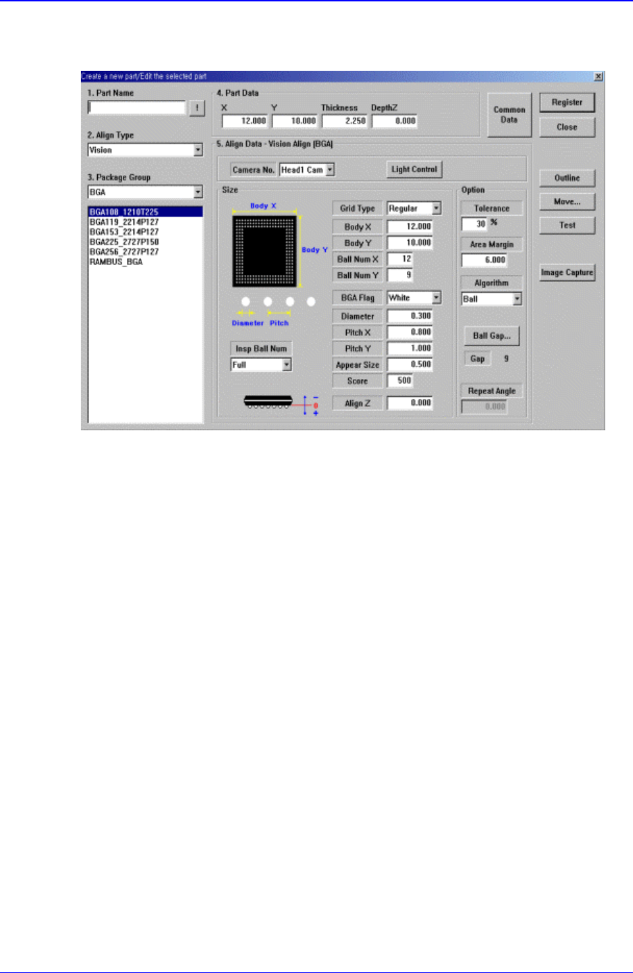
11.1.16. BGA component data setting
Set the align data for BGA components.
Figure 11-43. “Align Type = Vision, Package Group = BGA” dialog box
<Camera No.> combo box
Select the camera to recognize the component.
<Light Control> button
Set the light for the camera to recognize the component.
<Size> group
Set the align size.
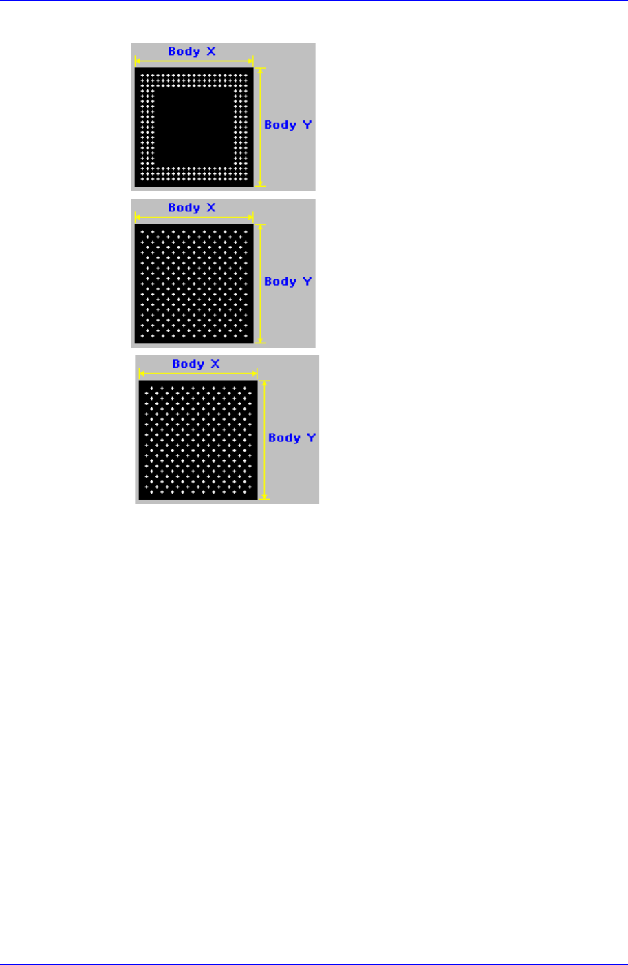
<Grid Type> combo box
PCB Edit Command
11-69
Select the ball array of BGA components. Available types are as follows.
Regular
Check
.
Rev. Check (Reverse Check)
<Body X> edit box
Set the size of component body in X direction.
<Body Y> edit box
Set the size of component body in Y direction.
<Ball Num X> edit box
Set the number of balls in X direction. In the case of “Check” or “Rev. Check”
type, the empty area is also included. Therefore, in the case of “Check” or “Rev.
Check” type, the number of balls is always an odd number.
<Ball Num Y> edit box
Set the number of balls in Y direction. In the case of “Check” or “Rev. Check”
type, the empty area is also included. Therefore, in the case of “Check” or “Rev.
Check” type, the number of balls is always an odd number.
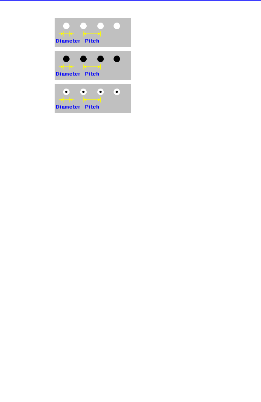
<BGA Flag> combo box
Samsung Component Placer CP-45F(V)/FS Operations Manual
11-70
Select the color of balls. Available colors are as follows.
White: for when the ball looks white.
Black: for when the ball looks black.
W & B (White and Black): for when the center of
the ball looks black and the outer side looks white.
<Diameter> edit box
Set the diameter of the ball.
<Pitch> edit box
Set the distance from the center of a ball to the center of the next ball..
In the case of “Check” or “Rev. Check”, set as if there are balls in the empty area.
<Appear Size> edit box
The ratio between the actual ball size and the size seen in the vision image. For
example, if the value is 1, then the ball is seen in its actual size, and if the value
is 0.9, then the ball is seen at 90% of its actual size.
<Score> edit box
When a ball is searched, the degree of conformity to the specifications is shown
as a score. 1000 means total conformity. But in reality, it is best to use about 600.
If you set a lower value, it can adversely affect recognition. And if you set too
high a score, the rejection rate increases.
<Align Z> edit box
Set the height for recognition. Based on the component surface, if the top is to be
recognizd, set - value and if the bottom is to be recognized, set + value.
<Option> group
Set the align option data.
<Area Margin> edit box
Set the limit for the image to be off the center of the screen when the component
is recognized. For example, if this value is 5mm, then the image of the
component should be within 5mm of the center of the screen.
<Tolerance> edit box
Tolerance for the ball. Set it as a percentage of <Ball Pitch>.
<Algorithm> edit box