operation-cp45.pdf - 第230页
Samsung Component Placer CP-45F(V)/FS Operations Manual 11-76 Select the component to install in the corresponding slot . When the <Part> column is clicked on, the combo box appears, and of the components registere…
PCB Edit Command
11-75
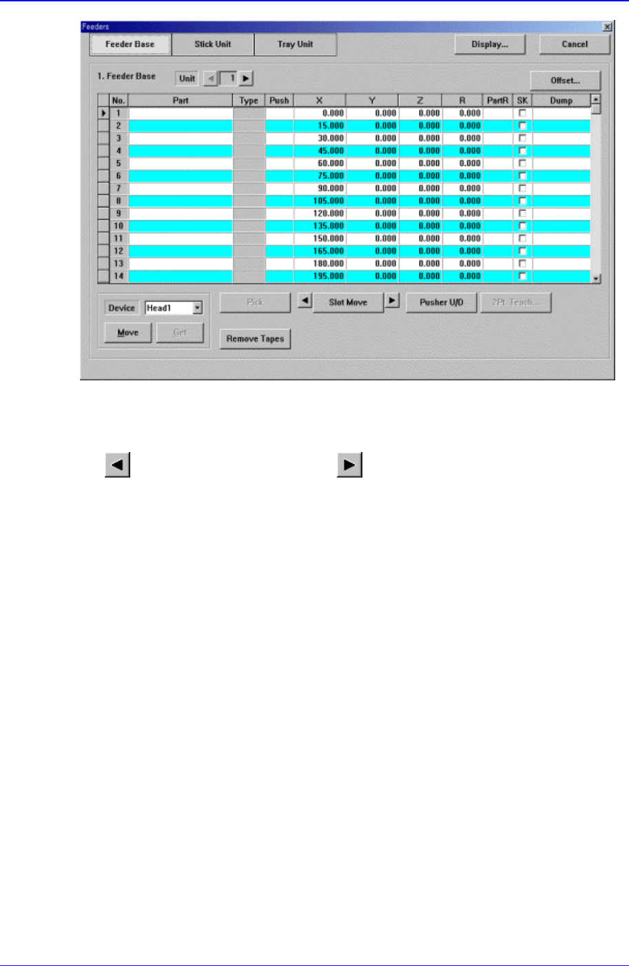
Figure 11-47.. “Feeder : Feeder Base” dialog box
<Unit> group
Select the feeder base unit to edit.
button selects the previous unit, button selects the next unit.
<1. Feeder Base> group
Display the status of various devices installed on the feeder base including the feeder
type and edit the installation position.
<No> column
A serial number of the feeder base slot. Air pressure type feeder base has 52 slots.
<Part> column
Samsung Component Placer CP-45F(V)/FS Operations Manual
11-76
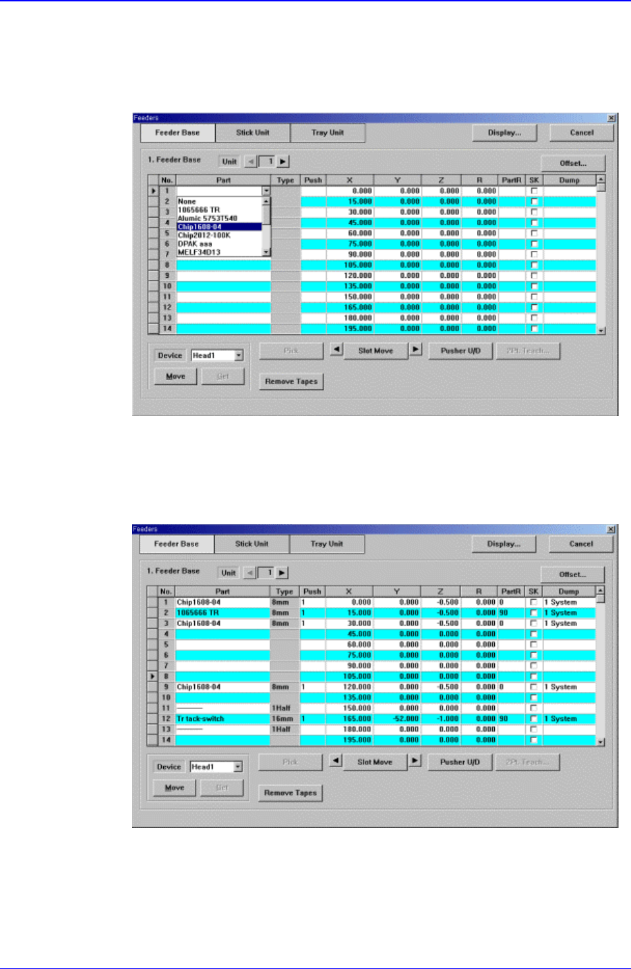
Select the component to install in the corresponding slot. When the <Part>
column is clicked on, the combo box appears, and of the components registered
in <1.2 Part>, the list of components to be supplied to “Tape” is displayed. Select
the component to install in this list. Next is the screen that shows selection of
components in the combo box of <Part> column.
Figure 11-48. “Feeder : When the part is selected in the Feeder Base” screen
<Type> column
Displays the type of the device installed in the corresponding slot. Next screen
shows the content displayed in the <Type> column of the feeder base on which
various devices are installed.
Figure 11-49. “Feeder : When various devices are installed in the Feeder Base” screen
PCB Edit Command
11-77
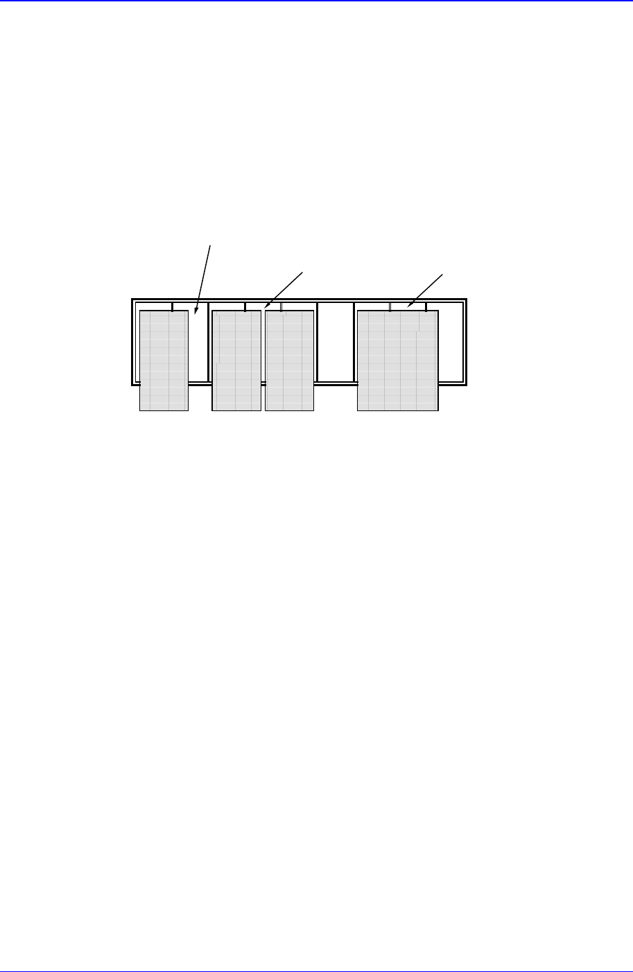
Of the items displayed in the <Type> column, explanation is given on the
following.
1Half: The corresponding slot is occupied by 1 device installed in the adjacent
slot.
2Half: The corresponding slot is occupied by 2 devices installed in the adjacent
slot.
Full: The corresponding slot is entirely occupied by the device installed in the
adjacent slot.
1
half status slot
2
half status slot
Full status slot
<Push> column
When the tape feeder is installed in the corresponding slot, select the number of
pushes necessary to push forward the tape feeder for 1 pitch.
<X> column
When the tape feeder is installed in the corresponding slot, set the X position to
pick up the component supplied from the tape feeder.
<Y> column
When the tape feeder is installed in the corresponding slot, set the Y position to
pick up the component supplied from the tape feeder.
<Z> column
When the tape feeder is installed in the corresponding slot, set the Z position to
pick up the component supplied from the tape feeder.
<R> column
When the tape feeder is installed in the corresponding slot, set the R
position(rotation angle of the head) to pick up the component supplied from the
tape feeder.
<PartR> column
When the tape feeder is installed in the corresponding slot, set the ing angle for
the component supplied from the tape feeder.