operation-cp45.pdf - 第304页
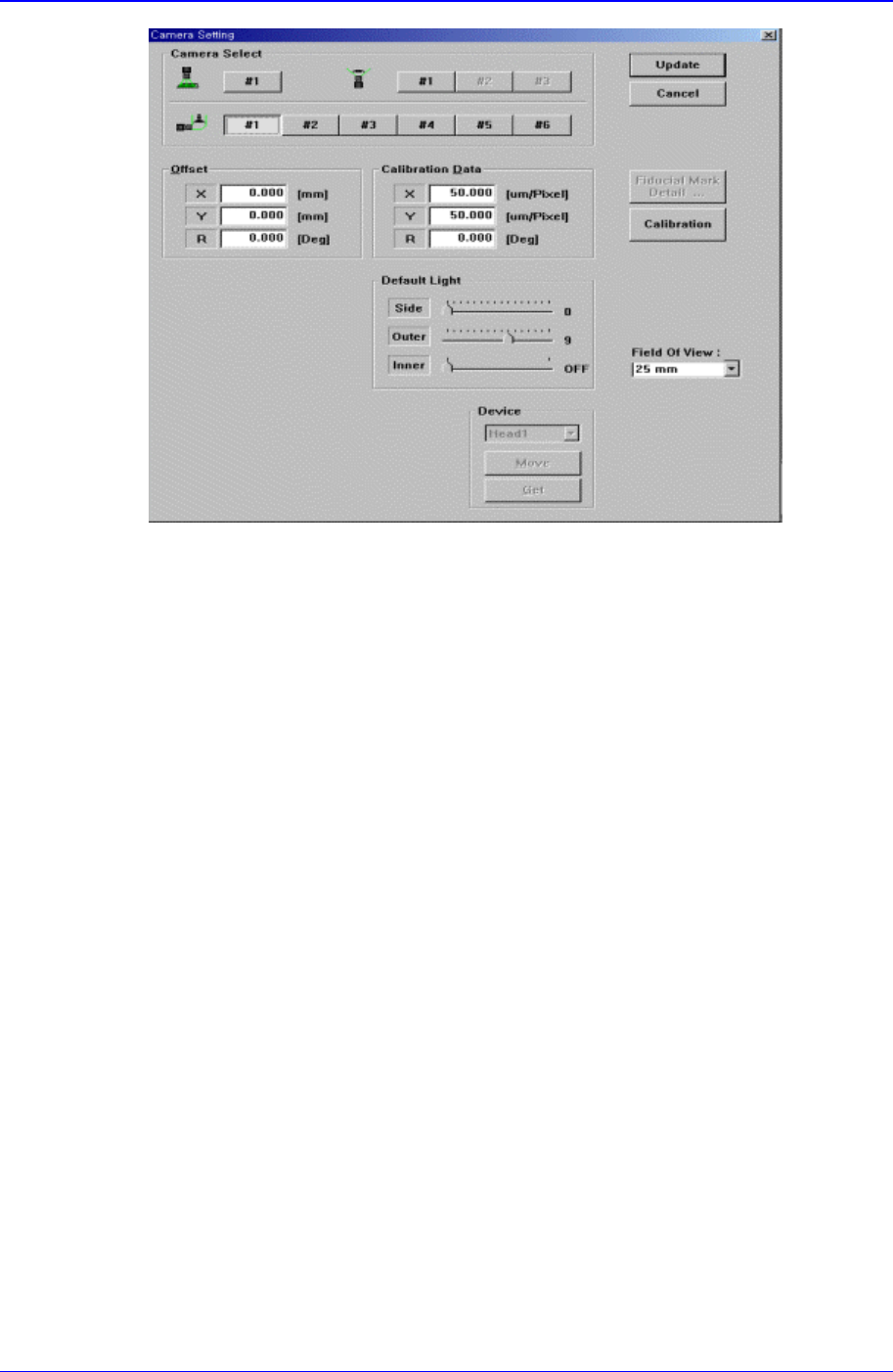
Samsung Component Placer CP-45F(V)/FS Operations Manual 15-18 <Calibration Data> group Set the camera calibration data. It can be set directly or by using the calibration function. <X> edit box Set the re…

Sys.Setup Command
15-17
function.
<X> edit box
Set the resolution of the camera in X direction. The unit is the number of pixels
per mm.
<Y> edit box
Set the resolution of the camera in Y direction. The unit is the number of pixels
per mm.
<R> edit box
Set the resolution of the camera in R direction. The unit is degree.
<Offset> group
Set the camera offset data.
<X> edit box
Set the offset value of the camera in X direction.
<Y> edit box
Set the offset value of the camera in Y direction.
<R> edit box
Set the offset value of the camera in R direction.
<Default Light> group
Set the default light value. Lights to be set are side light, outer light, and inner light.
<Position> group
Set the position of the fix camera.
<X> edit box
Set the X position value of the fix camera.
<Y> edit box
Set the Y position value of the fix camera.
<Z> edit box
Set the Z position value of the fix camera.
<R> edit box
Set the R position value of the fix camera.
<Feeder Base Lane> combo box
As the fix camera is fixed and installed on the feeder lane, set the fixed feeder lane.
It is always fixed to “Rear”.
<Not Usable Lane> edit box
Set the lane occupied by the fix camera.
Next screen is the case where the camera type is set to “Fly Camera”.
Samsung Component Placer CP-45F(V)/FS Operations Manual
15-18
<Calibration Data> group
Set the camera calibration data. It can be set directly or by using the calibration
function.
<X> edit box
Set the resolution of the camera in X direction. The unit is the number of pixels
per mm.
<Y> edit box
Set the resolution of the camera in Y direction. The unit is the number of pixels
per mm.
<R> edit box
Set the resolution of the camera in R direction. The unit is degree.
<Offset> group
Set the camera offset data.
<X> edit box
Set the offset value of the camera in X direction.
<Y> edit box
Set the offset value of the camera in Y direction.
<R> edit box
Set the offset value of the camera in R direction.
<Default Light> group
Set the default light value. Lights to be set are side light, outer light, and inner light.
<Device> combo box
To move or to read in the position of X,Y, Z, and R axes, select the corresponding
device. Available devices are as follows.
Move Cam: Selects Teaching Camera.
Head1: Selects Head1.
Sys.Setup Command
15-19
Head2: Selects Head2.
Head3: Selects Head3.
Head4: Selects Head4.
Head5: Selects Head5.
Head6: Selects Head6.
<Move> button
Moves the XY, Z, and R axes to the device selected in <Device>. At this time, the
edit box corresponding to the position to be read must be clicked on by a mouse.
<Get> button
Reads in the current position of the XY, Z, and R axes of the device selected in
<Device>.
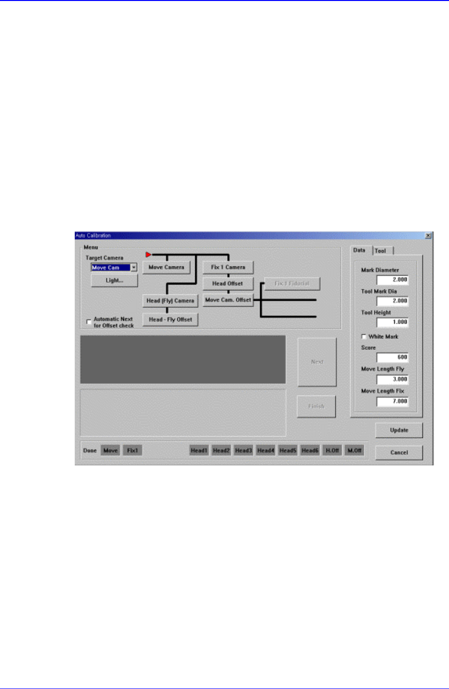
<Calibration> button
Performs the camera calibration function. When this button is clicked on, the
following screen is displayed.
<Camera> combo box
Select the camera to set light value.
<Light…> button
Set the light value for the selected camera..
<Menu> group
Select the items to calibrate.
<Fiducial Camera> button
Calibrates the move camera..
<Fix Camera> button
Calibrates the fix camera.
<Fly Camera> button
Calibrates the fly camera.