operation-cp45.pdf - 第115页
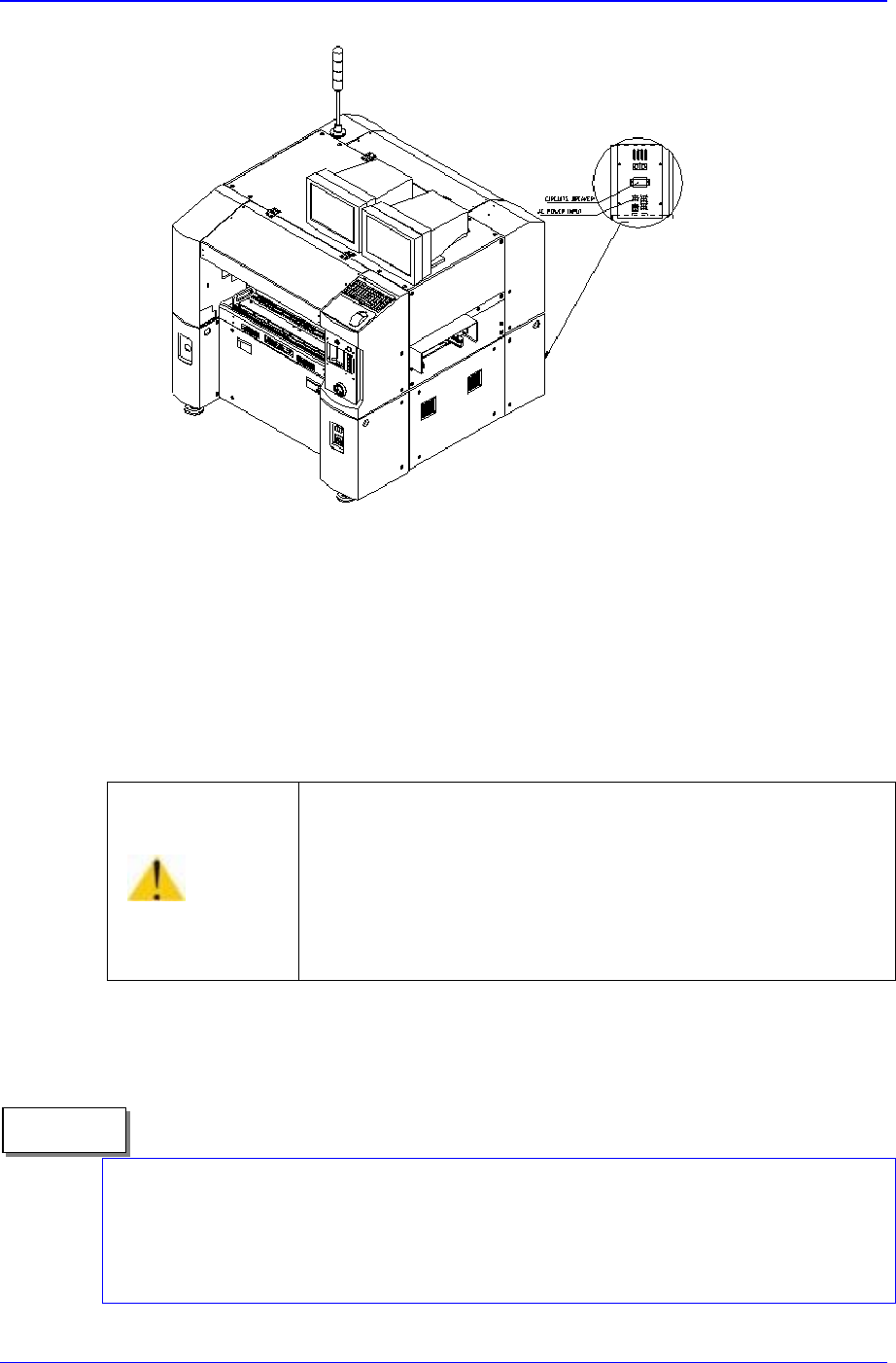
T ransfer & Installation Pr ocedur e 5-7 Figur e 5-6. AC power Input Connection 16. V erify once again prior to elevating the main circuit breaker that there is no obstacle in the conveyor or in the interior of the e…
Samsung Component Placer CP-45F(V)/FS Operations Manual
5-6
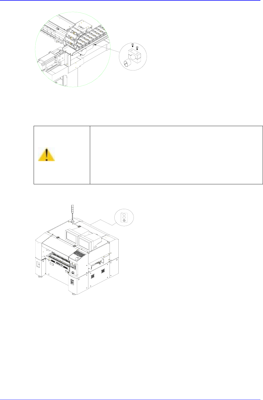
Figure 5-4. Method of Removing Clamp Y
10. Remove cable ties bound to the Z-axis, if necessary.
11. S
upply air pressure to the main air inlet.
Figure 5-5. Air Pressure Supply to the Main Air Inlet
12. Adjust air pressure to about 5 bars by turning the handle of a regulator.
13. Ensure the equipment power is properly connected according to the conditions for
your usage.
14. Measure the voltage value of your power supply with voltmeter and adjust to
equipment power condition.
15. The plug of power supply cable shall be connected to the outlet installed circuit
breaker in your company.
Caution
If the machine is operated when the cable Ties tied up to
the Z axis has not been removed, the machine could be
damaged.
Be sure to remove the cable ties tied up to the Z axis before
supplying power.
Transfer & Installation Procedure
5-7
Figure 5-6. AC power Input Connection
16. Verify once again prior to elevating the main circuit breaker that there is no obstacle
in the conveyor or in the interior of the equipment.
17. Then turn on the main circuit breaker of the equipment.
18. Turn the main <Isolation> switch of the equipment to ON position. Refer to
Figure3-1.
19. T
u
rn on <Main Start> switch located above the main <Isolation> switch after the
program is loaded. Refer to Figure3-1.
When the program is loading, the “I/O DPRAM Initialization Error” may occur because
the <Emergency> switch of the front and/or rear side of main body are released. Please
check if the <Emergency> switch of the front and/or rear side of main body are released
when the program is loading by turning on the <Main Start> switch.
Caution
If power supply and inside of the machine are not checked
before lifting the Main Circuit breaker, the machine can be
damaged or injury could occur.
Be sure to check power supply and inside of the machine
before lifting the Main Circuit breaker.
Memo
Samsung Component Placer CP-45F(V)/FS Operations Manual
5-8
20. Press <Ready> switch on the front operation panel after the loading of the whole
program is completed.
21. Push the X frame and traveling unit in the direction of the Middle of X axis just a bit,
and then move the moving parts of the equipment to the home position by using the
teaching box.
22. Expand the conveyor width as much as necessary by using the teaching box.
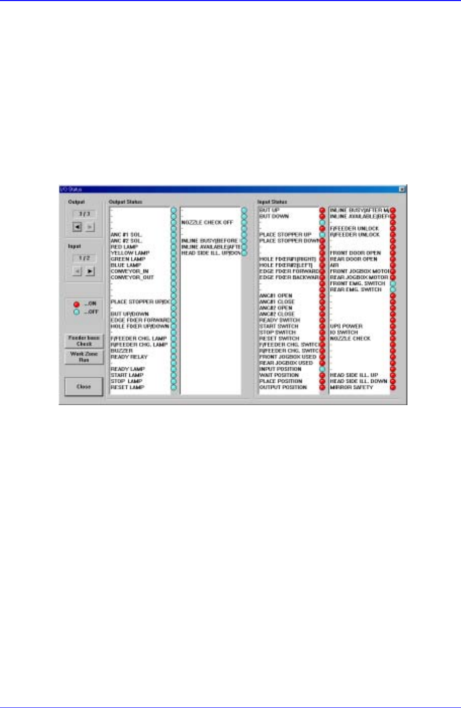
23. Select <Diagnosis> from the main menu tool-bar and open the “I/O Status” dialog
box by clicking “<I/O>(F2)” on the sub menu tool-bar.
Figure 5-7. “I/O Status” dialog box
24. Select <Conveyor IN/OUT> item from the <Output> list box.
25. Insert the test board through the conveyor entrance as the conveyor begins to run.
26. In the <Input> list box, verify that the board detection sensor of each section is
operating properly.
27. For using the equipment through In-line, connect communication cables supplied in
SMEMA IN/OUT port to effect a proper communication between the equipment
parts for the former and latter processes.
28. If everything is normal, operate the equipment by following the production procedure.