operation-cp45.pdf - 第251页
PCB Edit Command 1 1-97 To move the XY axis or to read in th e current position of the XY axis, select the corresponding device. Available devices are as follows. Move Cam: Selects Teaching Camera. Head1: Selects Head1. …
Samsung Component Placer CP-45F(V)/FS Operations Manual
11-96
Set the string of characters to find. At this time, the column in the grid containing
the string of characters must be specified first.
<Find Prev>
button
Finds the string of characters set in the edit box in the previous lines of the
current line of the column specified in the grid.
<Find Next>
button
Finds the string of characters set in the edit box in the next lines of the current
line of the column specified in the grid.
<2Pt. Teach> button
When a placement position is set, performs the function of teaching 2 corner points,
calculating the center point and using it as the placement point. When this button is
clicked on, the following dialog box is displayed.
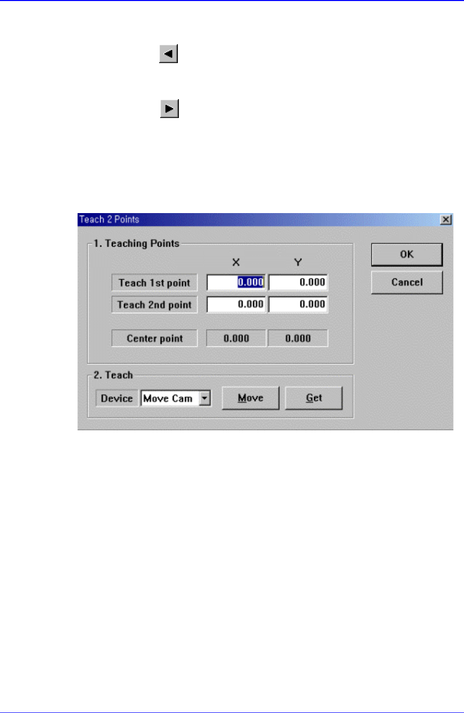
Figure 11-55. “Step: Teach 2 Points” dialog box
<1. Teaching Points> group
Set the positions of two corner points to obtain the center point.
Teach 1st point: Set the position of the first point.
Teach 2nd point: Set the position of the second point.
Center point: Displays the center point by using the positions of two corner
points.
<2. Teach> group
Used to move the XY axis of the equipment to the specified position or to read in
the current position of the XY axis.
<Device> combo box
PCB Edit Command
11-97
To move the XY axis or to read in the current position of the XY axis, select the
corresponding device. Available devices are as follows.
Move Cam: Selects Teaching Camera.
Head1: Selects Head1.
Head2: Selects Head2.
Head3: Selects Head3.
Head4: Selects Head4.
Head5: Selects Head5.
Head6: Selects Head6.
<Move> button:
Moves the XY axis to the device selected in <Device>. Before executing “Move”,
the edit box corresponding to the desired position must be clicked on with a
mouse.
<Get> button:
Reads in the current position of the XY axis of the device selected in <Device>.
Before executing “Get”, the edit box corresponding to the desired position must
be clicked on with a mouse.
<OK> button
Sets the obtained center point as the new pickups point and closes the dialog box.
<Cancel> button
Ignores the obtained center point and closes the dialog box.
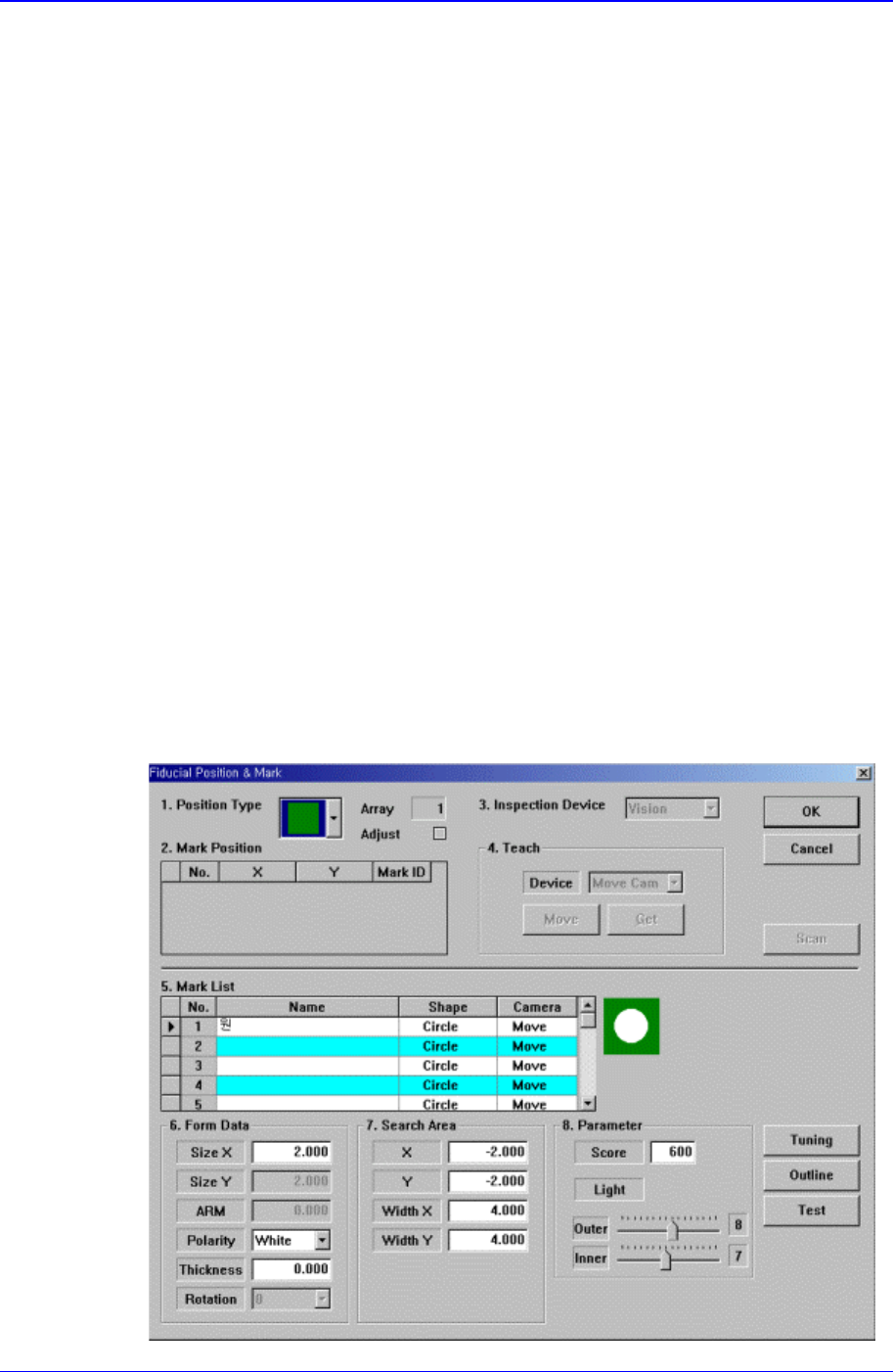
<Fiducial…> button
If the placement point has a fiducial mark, sets the fiducial mark data. When this
button is clicked on, the following dialog box is displayed.
Samsung Component Placer CP-45F(V)/FS Operations Manual
11-98
<Position Type> combo box
Select the number of fiducial marks. Available numbers of fiducial marks are as
follows.
None: No fiducial mark.
1 Part: 1 fiducial mark for placement point adjustment.
2 Part: 2 fiducial marks for placement point adjustment.
For the rest, please refer to the explanation of the <Fiducial Mark…> button in
<11.1 Board>.
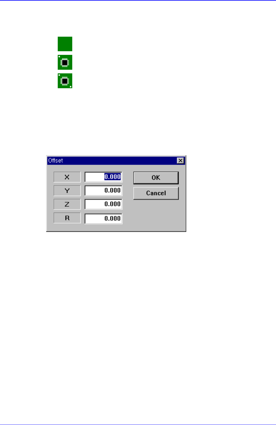
<Offset…> button
Adds the offset value to the position of placement point. Before executing this
function, the line to add the offset value must be selected in the grid. When this
button is clicked on, the following dialog box is displayed.
<X> edit box
Set the X offset value.
<Y> edit box
Set the Y offset value.
<Z> edit box
Set the Z offset value.
<R> edit box
Set the R offset value.
<OK> button
Closes the dialog box and adds the set offset value to the selected line in the grid.
<Cancel> button
Ignores the set offset value and closes the dialog box
<Adjust…> button
It is a function used to change the PCB step coordinate or to check and adjust the gap
between the previous fiducial mark coordinate and the current fiducial mark
coordinate to use the previous step coordinate when the backup table is down
accidentally.
<Insert 1Line> button