operation-cp45.pdf - 第288页
Samsung Component Placer CP-45F(V)/FS Operations Manual 15-2 Figur e 15-3. “ Sys. Setup : Gantry / Head Inf ormation ” dialog box <Gantry ID> Static box Displays the ID of the gantry to which the head block is at…
Sys.Setup Command
15-1
Chapter 15. Sys.Setup Command
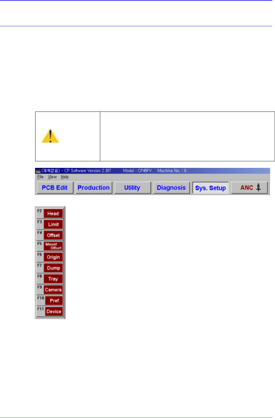
The Sys. Setup command is composed of ten submenus: Head, Limit, Offset, Mount
Offset, Origin, Dump, Tray, Camera, Pref., and Device.
This command is used to check and change the various set up status of the equipment.
When the set up status is set improperly, it could cause dangerous situations during
equipment operation. To prevent improper handling by unauthorized personnel, a
password must be entered.
When a submenu of the <Sys. Setup> command is selected, corresponding dialog box is
displayed on the screen. While the corresponding dialog box is displayed, selecting the
menu once more activates the dialog box.
Figure 15-1. When the Sys. Setup Command is Selected
Figure 15-2. Submenus of the Sys. Setup command
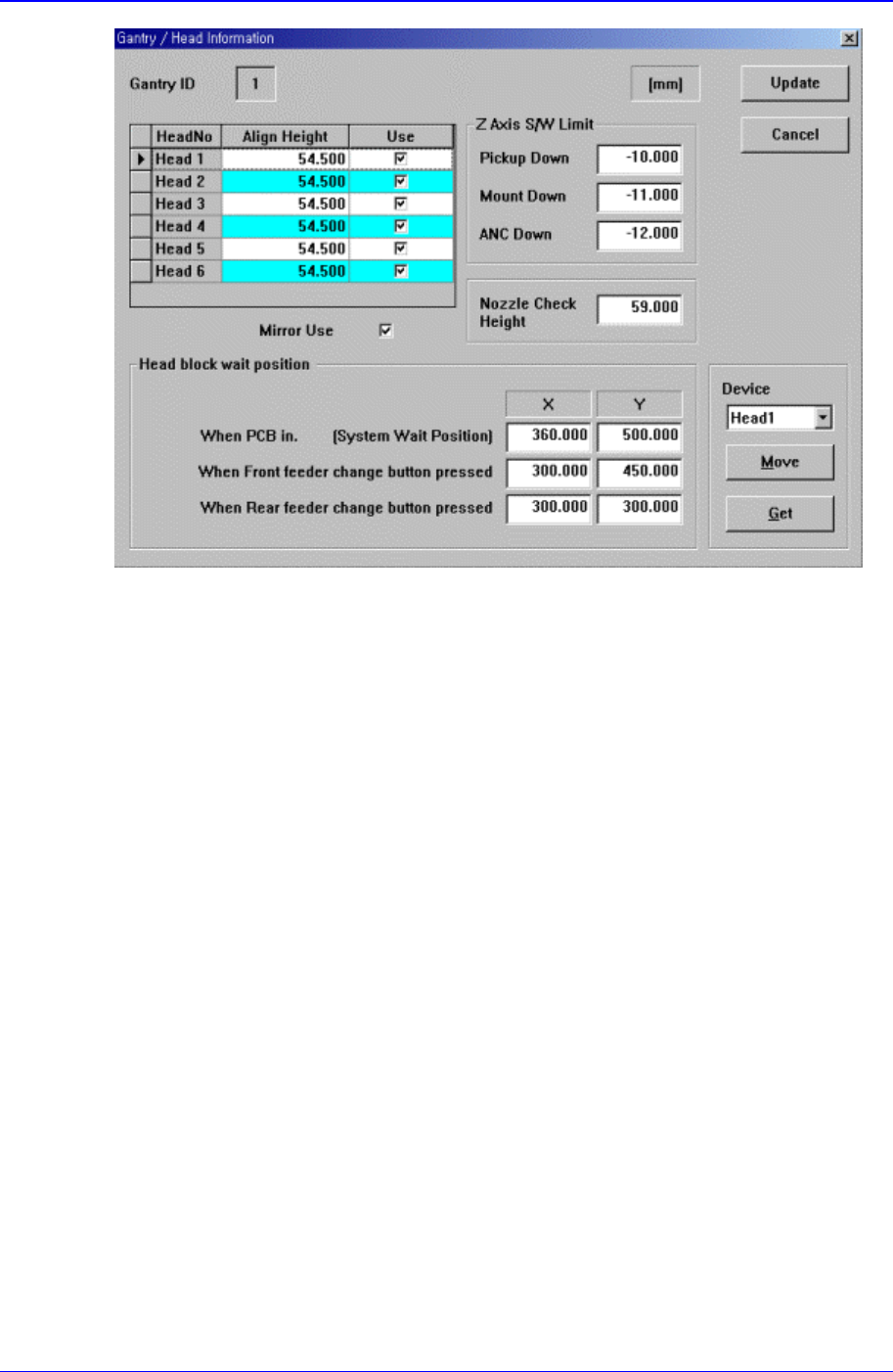
15.1. Head [F2]
The <Head> command displays and sets the status of the head block.
When this button is clicked on, the following dialog box is displayed.
Warning
Changing the set up status by an unauthorized user could
damage the machine or result in personal injury.
Unauthorized user must not change the set up status of
the machine.
Samsung Component Placer CP-45F(V)/FS Operations Manual
15-2
Figure 15-3. “Sys. Setup : Gantry / Head Information” dialog box
<Gantry ID> Static box
Displays the ID of the gantry to which the head block is attached.
<Grid> group
Set the data on the head.
<Head No> column
Displays the head number.
<Align Height> column
Set the align height.
<Z Axis S/W Limit> group
Set the height limit for Z axis movement. when the PCB board is loaded the surface
of the PCB board is determined as the base position of this limit value.
<Pickup Down> edit box
Set the limit for Z axis height when the Z axis is lowered for component pickups.
< Down> edit box
Set the limit for Z axis height when the Z axis is lowered for component pickups.
<ANC Down> edit box
Set the limit for Z axis height when the Z axis is lowered for nozzle change in the
ANC.
<Nozzle Check Height> edit box
Set the limit for Z axis height to check component pickups by the nozzle.
<Head block wait position> group
Set the waiting position for the head block.
<When PCB in> edit box

Sys.Setup Command
15-3
Set the waiting position for the head block when the PCB is being loaded.
<When Front feeder change button pressed> edit box
When the “Front feeder change” button on the front operation panel of the
equipment is pressed, set the waiting position for the head block.
<When Rear feeder change button pressed> edit box
When the “Rear feeder change” button on the rear operation panel of the
equipment is pressed, set the waiting position for the head block.
<Device> combo box
To move or to read in the position of the XY, and Z axes, select the corresponding
device. Available devices are as follows.
Move Cam: Selects Teaching Camera.
Head1: Selects Head1.
Head2: Selects Head2.
Head3: Selects Head3.
Head4: Selects Head4.
Head5: Selects Head5.
Head6: Selects Head6.
<Move> button
Moves the XY and Z axes to the device selected in <Device>. At this time, the edit
box corresponding to the position to move to must be clicked on with a mouse.
<Get> button
Reads in the current position of XY, and Z axes of the device selected in <Device>.
At this time, the edit box corresponding to the position to be read must be clicked on
with a mouse.
<Update> button
Transmits the set data to the equipment and closes the dialog box.
<Cancel> button
Ignores the set data and closes the dialog box.
15.2. Limit [F3]
The <Limit> command sets the limit position of each axis to move.
When this button is clicked on, the following dialog box is displayed.