operation-cp45.pdf - 第42页
Samsung Component Placer CP-45F(V)/FS Operations Manual 1-4 1.2.2.2. Stage vision recogniti on system(For CP-45FV /45FS) T able 1-3. Applicable Component Sizes (V ision Recognition System) CP-45FV / 45FS Option Classific…
Features and Scope of Equipment
1-3
1.2. Applicable Components and Packages
1.2.1. Configuration of the head and vision recognition system
The vision recognition systems of the CP-45F/V and CP-45FS related to the
components placed are as shown in Table 1-1
Table 1-1. Configuration of the Head and Vision Recognition System
Head Structure
Classification
Head 1 Head 2 Head 3 Head 4 Head 5 Head 6
Vision
System
CP-45FV
25mm
Vision
25mm
Vision
25mm
Vision
25mm
Vision
25mm
Vision
25mm
Vision
- 35mm
Vision
CP-45F
25mm
Vision
25mm
Vision
25mm
Vision
25mm
Vision
25mm
Vision
25mm
Vision
CP-45FS
15mm
Vision
15mm
Vision
15mm
Vision
15mm
Vision
15mm
Vision
15mm
Vision
- 35mm
Vision
CP-45FS has six 15mm flying vision cameras for placing the components requiring
precision (0603 Chip, □ 12mm.), and The 20mm , 45mm Stage Vision recognition
systems can be used simply by replacing the upward vision unit. (Please refer to “1.2.2
Applicable component sizes (page 1-3).”)
1.2.2. Applicable component sizes
1.2.2.1. Flying vision recognition system
The sizes of components applicable to this equipment are prescribed in Table 1-2, and is
applicable to general components usage as well.
Table 1-2. Applicable Component Sizes (vision recognition system)
CP-45FV
CP-45FS
Classification
Standard ( FOV 25mm Lens) (FOV 15mm Lens)
Chips 1005 ~ 0603 ~
IC, Connector
~□ 22.0mm , Lead Pitch : 0.5mm ~□ 12.0mm , Lead Pitch : 0.5mm
BGA,CSP
~□ 17.0mm, Ball Pitch : 0.75mm ~□ 12.0mm , Lead Pitch : 0.75mm
Memo

Samsung Component Placer CP-45F(V)/FS Operations Manual
1-4
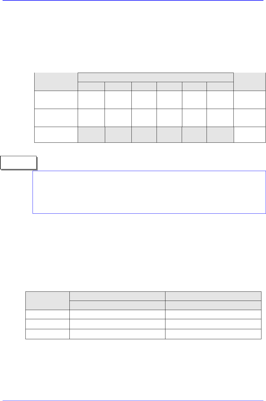
1.2.2.2. Stage vision recognition system(For CP-45FV /45FS)
Table 1-3. Applicable Component Sizes (Vision Recognition System)
CP-45FV / 45FS
Option
Classification
Standard
FOV35mm
FOV20mm FOV45mm
IC , Connector
~ □ 17mm: 0.3 mm pitch
~ □ 32mm: 0.4 mm pitch
~ □ 40mm: 0.5 mm pitch
( MFOV for more than
32mm)
Chips 1005~
~ □ 17mm: 0.3 mm
pitch
~ □ 32mm: 0.4 mm pitch
~ □ 42mm: 0.5 mm pitch
BGA
~ □ 32mm: 1.0mm pitch
~ □ 17mm: 0.5mm
pitch
~ □ 42mm: 1.0mm pitch
1.2.3. The placement precision
The placement precision for applicable components type is shown in Table 1-4, and is
applicable to general components usage as well.
Table 1-4. The placement Precision
Classification
Placement
precision
Remarks
Chip 0603
Chip 1005
± 0.08
± 0.1
FOV15mm Flying vision (CP-45FS)
± 0.065 FOV25mm Flying Vision(□ 25mm: 0.5 pitch)
QFP
± 0.040 FOV35mm Stage Vision(□ 17mm: 0.3 pitch)
± 0.065 FOV25mm Flying Vision(□ 17mm: 0.75 pitch)
BGA
± 0.080 FOV35mm Stage Vision(□ 32mm: 1.0 pitch)
± 0.065 FOV22mm flying Vision(□ 22mm: 0.5mm pitch)
Connector
± 0.05 FOV35mm Stage Vision(□ 32mm: 0.65mm pitch)
1.2.4. The pick & place cycle time
The descriptions given below refer to the best performance that can be obtained from the
pick & place cycle time. The actual cycle time can vary depending on the size of PCB,
frequency of the nozzle replacement, etc.
Features and Scope of Equipment
1-5
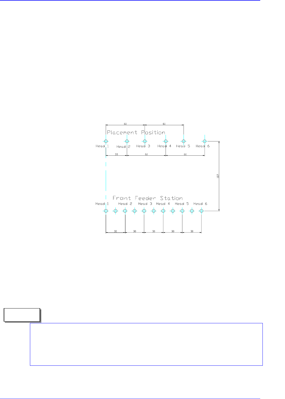
1.2.4.1. General features
Speed
The optimum condition for the tact time is specified.
The placed Component : 1608 chip
Time Measurement
The measured time from the first pickups to return of the machine to the original
position following the final placement.(Off-line time, i.e., the time for recognizing the
fiducial mark, or PCB feed time, is excluded.)
Figure 1-2. The Summary for Measuring the Tact Time (6 Heads Simultaneous Pickups, Each
heads place)
The above speed is for the pick & place cycle time under the optimum conditions
(rounded off to 1msec). The experimental conditions is under using a very new
equipment with a taped PCB at the factory site, therefore, in actual placement, it can vary
according to the placement conditions.
Memo