operation-cp45.pdf - 第54页
Samsung Component Placer CP-45F(V)/FS Operations Manual 2-2 2.2. System Configuration 2.2.1. Mechanical part configuration C P- 4 5 FV M e c ha n i c al Pa r t C on f i gu r a t i on BODY FRA M E Mirr or Driving Part Sid…
Basic Configuration and Name of Each Part
2-1
Chapter 2. Basic Configuration and Name
of Each Part
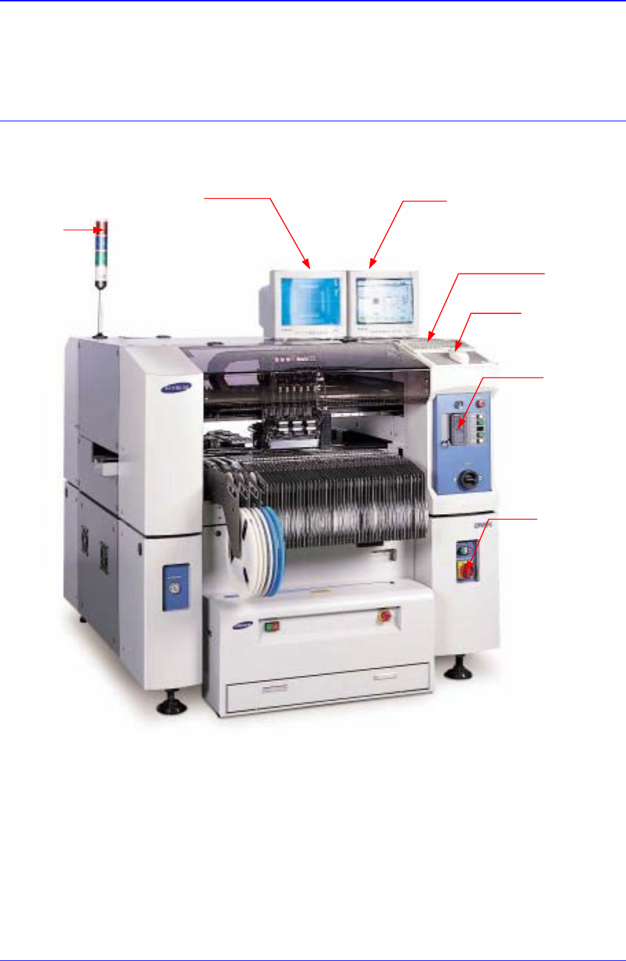
2.1. Exterior (Name of Each Part)
Figure 2-1. Equipment Exterior (Front View)
Programming Monitor
K
eyboa
r
d
Mouse
Teaching Box
Isolation Switch
Teaching Monitor
Signal Towe
r
Samsung Component Placer CP-45F(V)/FS Operations Manual
2-2
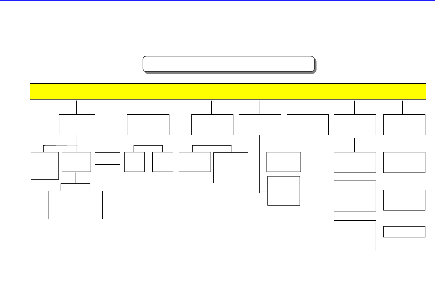
2.2. System Configuration
2.2.1. Mechanical part configuration
CP-45FV Mechanical Part Configuration
BODY FRAME
Mirror
Driving
Part
Side ILL.
Driving
Part
UPWARD
CAMERA
Electric Part &
COVER
35mm
CAMERA
CONTROL
BOX
45mm
CAMERA
(OPTION)
CONTROL
BOX
20mm
CAMERA
(OPTION)
COVER
FEEDER
BASE
HEAD
(6NOZZLE)
X-Y
GANTRY
X
AXIS
Y
AXIS
FLYING
CAMERA
UNIT
FIDUCIAL
CAMERA
UNIT
NOZZLE
Fixed ANC
(36POCKET)
Correct Tool
(1POCKET)
ANC
UNIT
3Stage
CONVEYOR
Driving-Motor
Adjust Width
(OPTION)
CONVEYOR
UNIT
Figure 2-2. Mechanical Part Configuration Diagram
Basic Configuration and Name of Each Part
2-3
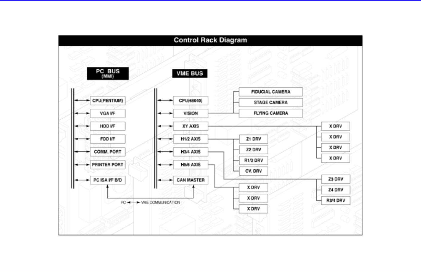
2.2.2. Control part configuration
Figure 2-3. Control Part Configuration Diagram