operation-cp45.pdf - 第156页
Samsung Component Placer CP-45F(V)/FS Operations Manual 11-2 Figur e 1 1-4. “ PCB Edit : Bo ar d Definition ” dialog box <1. Customer Name> edit box Enter the name of the customer who requested the PCB operation.…
PCB Edit Command
11-1
Chapter 11. PCB Edit Command
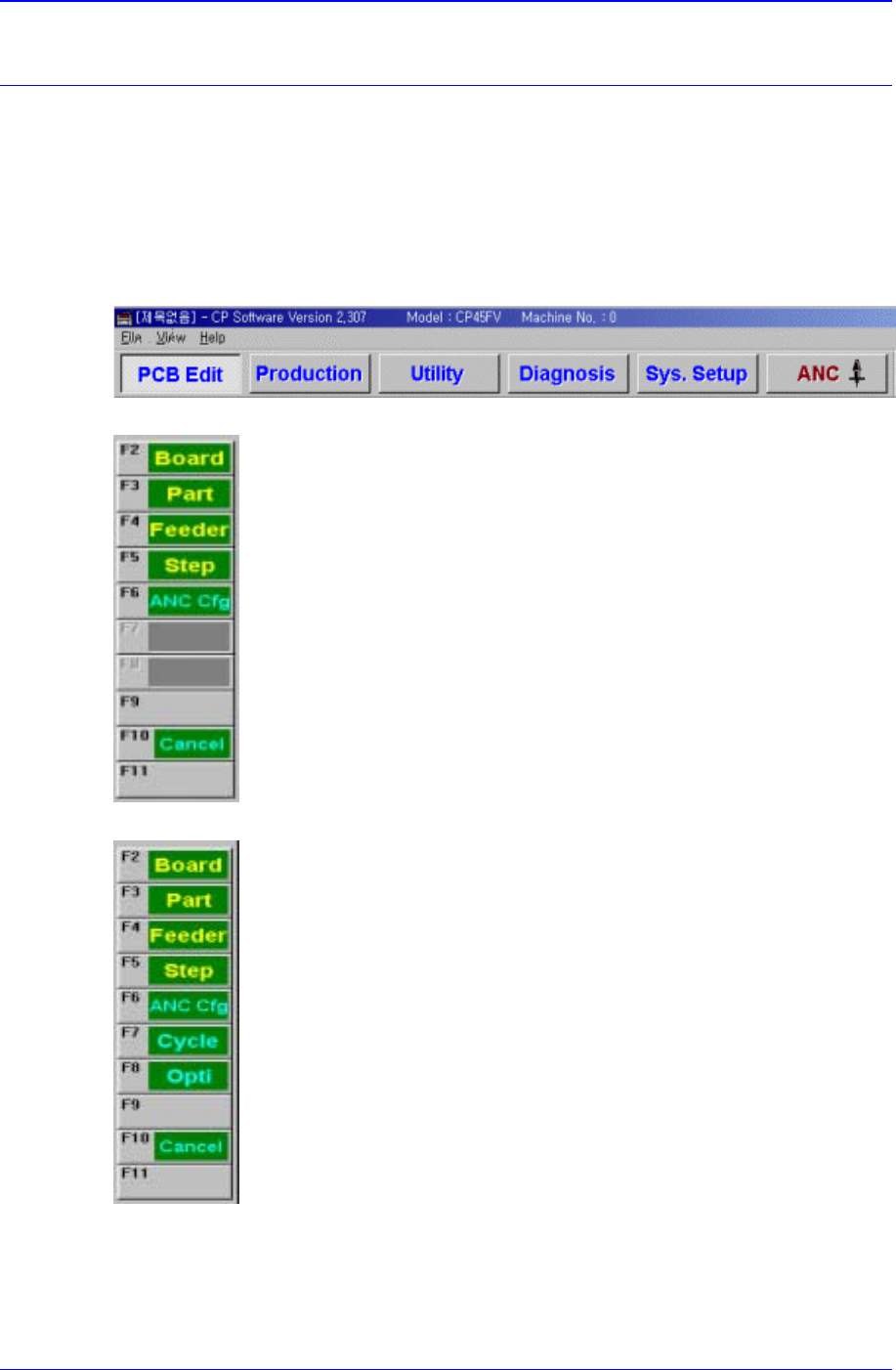
The <PCB Edit> Command is composed of the eight submenus: Board, Part, Feeder,
Step, ANC Cfg, Cycle, Opti, Cancel.
Used to edit data for the placement of components on a PCB (Printed Circuit Board ).
When a submenu of the <PCB Edit> command is selected, the corresponding dialog box
is displayed. While the dialog box corresponding to the submenu is displayed, if the menu
is selected again, the corresponding dialog box is activated. Click on the button on the top
right to close the dialog box.
Figure 11-1. When the PCB Edit command is selected
Figure 11-2. Submenus of the PCB Edit command(Initial status)
Figure 11-3. Sub menus of the PCB Edit command(Activated status)
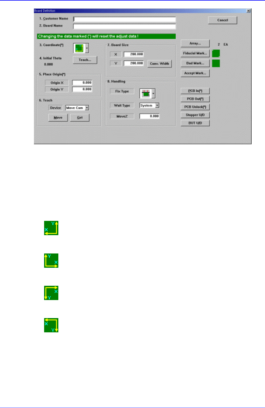
Use the <Board> command to edit the PCB (Printed Circuit Board) setup only. When this
button is selected, the following dialog box is displayed.
Samsung Component Placer CP-45F(V)/FS Operations Manual
11-2
Figure 11-4. “PCB Edit : Board Definition” dialog box
<1. Customer Name> edit box
Enter the name of the customer who requested the PCB operation. Up to 64
characters can be entered.
<2. Board Name> edit box
Enter the PCB name. Up to 64 characters can be entered.
<3. Coordinate> combo box
Select the PCB coordinate system. Available coordinate systems are as follows.
Left-Up : Based on the front of equipment, it is a coordinate system in which
the X axis increases to the left and the Y axis increases to the top.
Right-Up : Based on the front of equipment, it is a coordinate system in which
the X axis increases to the left and the Y axis increases to the top.
Left-Down : Based on the front of equipment, it is a coordinate system in
which the X axis increases to the left and the Y axis increases to the top.
Right-Down : Based on the front of equipment, it is a coordinate system in
which the X axis increases to the left and the Y axis increases to the top.
<4. Initial Theta >
Set the initial theta for board data editing. At this time, the PCB should be already
loaded in the operation area of the equipment.
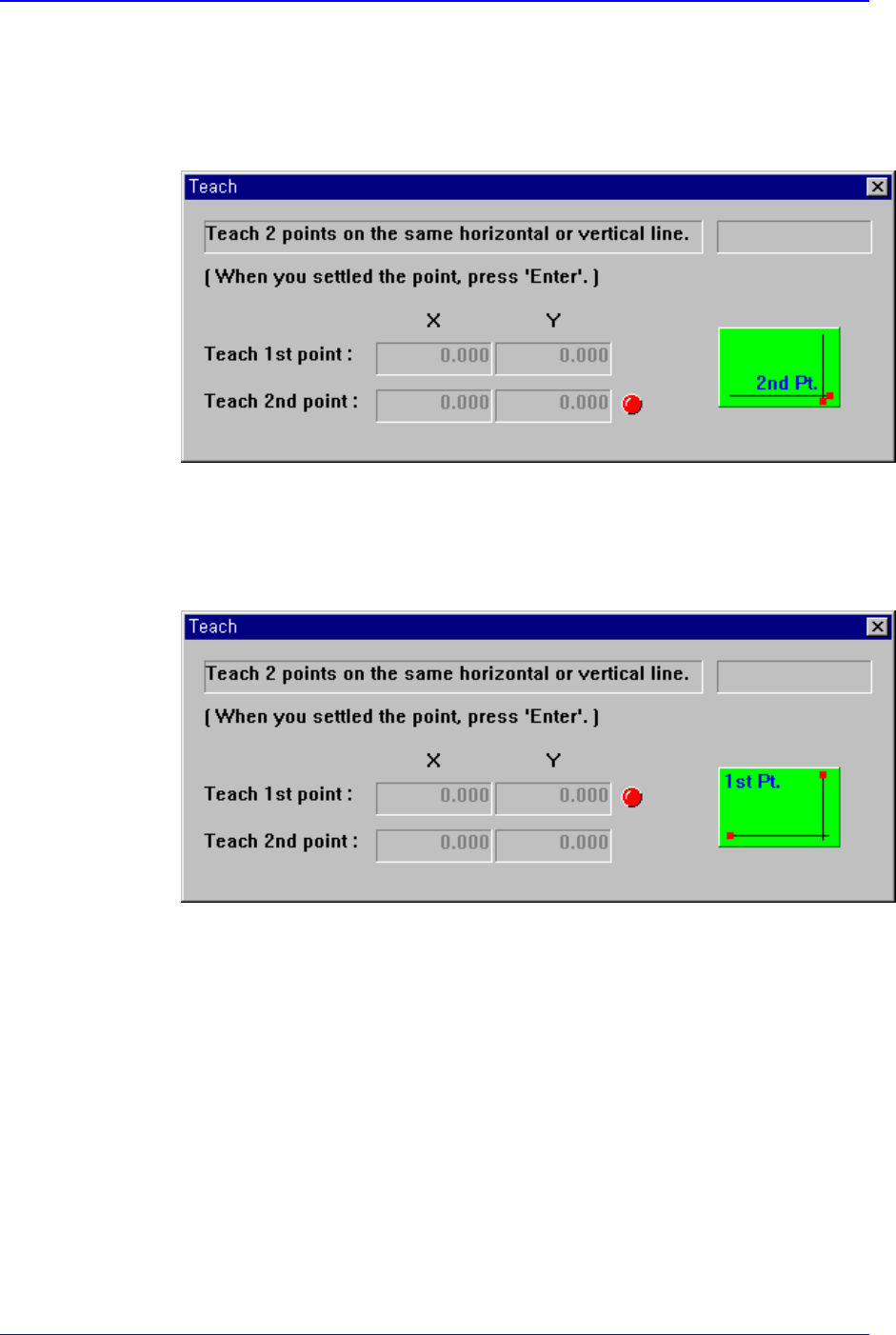
<Initial Theta - Teach> button
PCB Edit Command
11-3
It is activated when there is fiducial mark data.
This button is used to teach the initial theta of PCB. When this button is clicked
on, the following screens are displayed in succession.
When teaching the initial theta of PCB, teach two points on the same horizontal
or vertical line, then the initial theta of the PCB is calculated automatically.
Figure 11-5 Screen showing the first point teaching
Teach the first point of the two points on the same horizontal line or vertical line
on the PCB. When the “Enter” key is pressed after teaching, the following screen
is displayed.
Figure 11-6 Screen showing the second point teaching