operation-cp45.pdf - 第250页
Samsung Component Placer CP-45F(V)/FS Operations Manual 11-96 Set the string of characters to find. At this time, the co lumn in the grid containing the string of characters must be specified first. <Find Prev> b…
PCB Edit Command
11-95
in the grid
<Move Next>
button
Moves the XY axis to the placement point on the next line of the current line in
the grid.
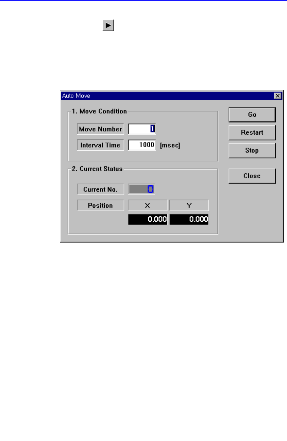
<Auto> check box
To move continuously, check this check box. When this check box has been
clicked on and <Move Prev> or <Move Next> is clicked on, the following dialog
box is displayed.
<1. Move Condition> group
Set the number of placement points to move and the time interval between
movement.
Move Number: Set the number of placement points to move continuously.
Interval Time: Set the time interval between placement point movements.
<2. Current Status> group
Displays the number and position of the current placement point.
Current No.: Displays the current placement point number.
Position X: Displays the X position of the current placement point.
Position Y: Displays the Y position of the current placement point.
<Adjust> check box
Displayed only when the fiducial mark has been set.
To move after adjusting by using the fiducial mark of the PCB, check this check
box.
<Find> group
Edit box
Samsung Component Placer CP-45F(V)/FS Operations Manual
11-96
Set the string of characters to find. At this time, the column in the grid containing
the string of characters must be specified first.
<Find Prev>
button
Finds the string of characters set in the edit box in the previous lines of the
current line of the column specified in the grid.
<Find Next>
button
Finds the string of characters set in the edit box in the next lines of the current
line of the column specified in the grid.
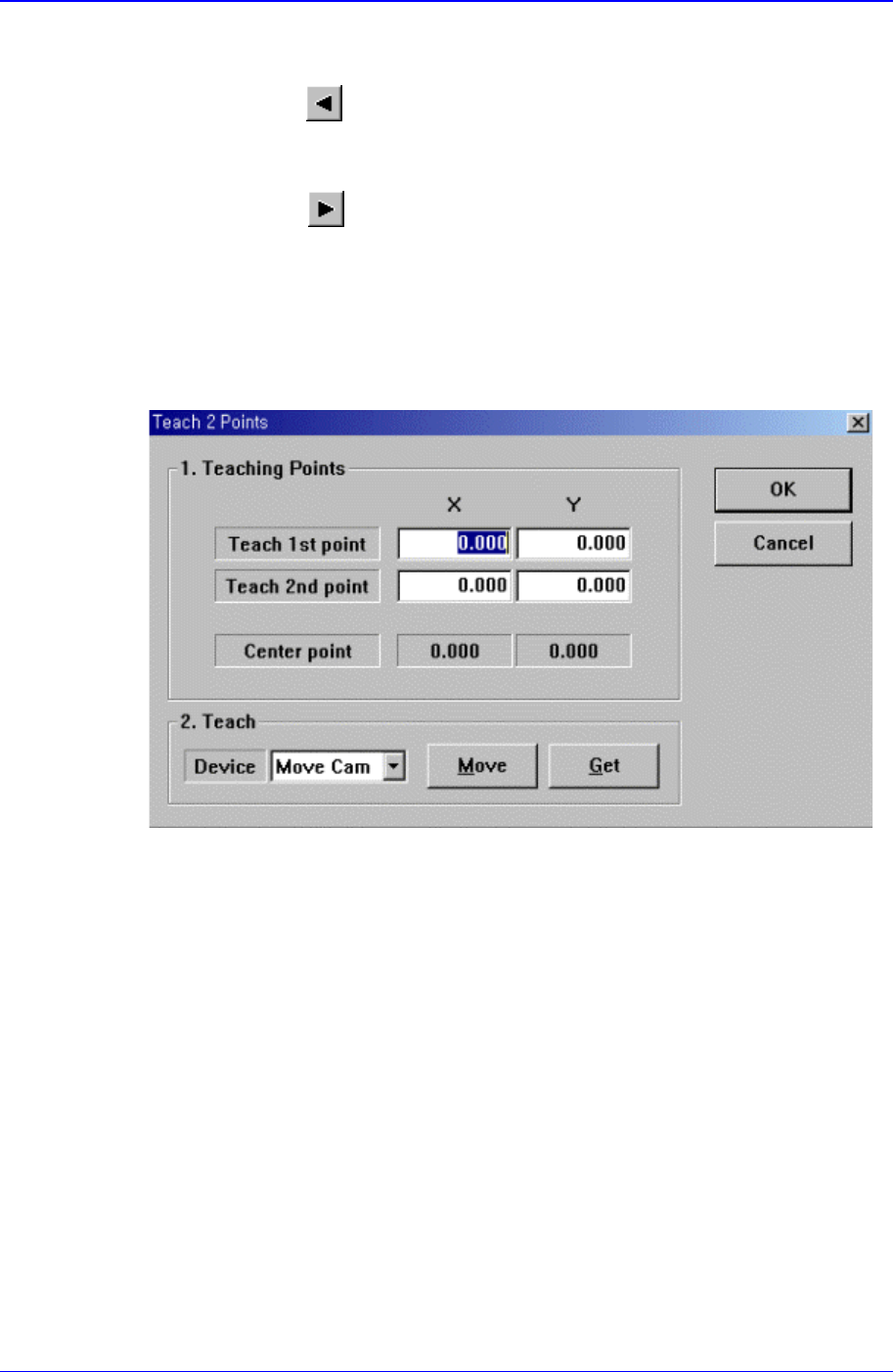
<2Pt. Teach> button
When a placement position is set, performs the function of teaching 2 corner points,
calculating the center point and using it as the placement point. When this button is
clicked on, the following dialog box is displayed.
Figure 11-55. “Step: Teach 2 Points” dialog box
<1. Teaching Points> group
Set the positions of two corner points to obtain the center point.
Teach 1st point: Set the position of the first point.
Teach 2nd point: Set the position of the second point.
Center point: Displays the center point by using the positions of two corner
points.
<2. Teach> group
Used to move the XY axis of the equipment to the specified position or to read in
the current position of the XY axis.
<Device> combo box
PCB Edit Command
11-97
To move the XY axis or to read in the current position of the XY axis, select the
corresponding device. Available devices are as follows.
Move Cam: Selects Teaching Camera.
Head1: Selects Head1.
Head2: Selects Head2.
Head3: Selects Head3.
Head4: Selects Head4.
Head5: Selects Head5.
Head6: Selects Head6.
<Move> button:
Moves the XY axis to the device selected in <Device>. Before executing “Move”,
the edit box corresponding to the desired position must be clicked on with a
mouse.
<Get> button:
Reads in the current position of the XY axis of the device selected in <Device>.
Before executing “Get”, the edit box corresponding to the desired position must
be clicked on with a mouse.
<OK> button
Sets the obtained center point as the new pickups point and closes the dialog box.
<Cancel> button
Ignores the obtained center point and closes the dialog box.
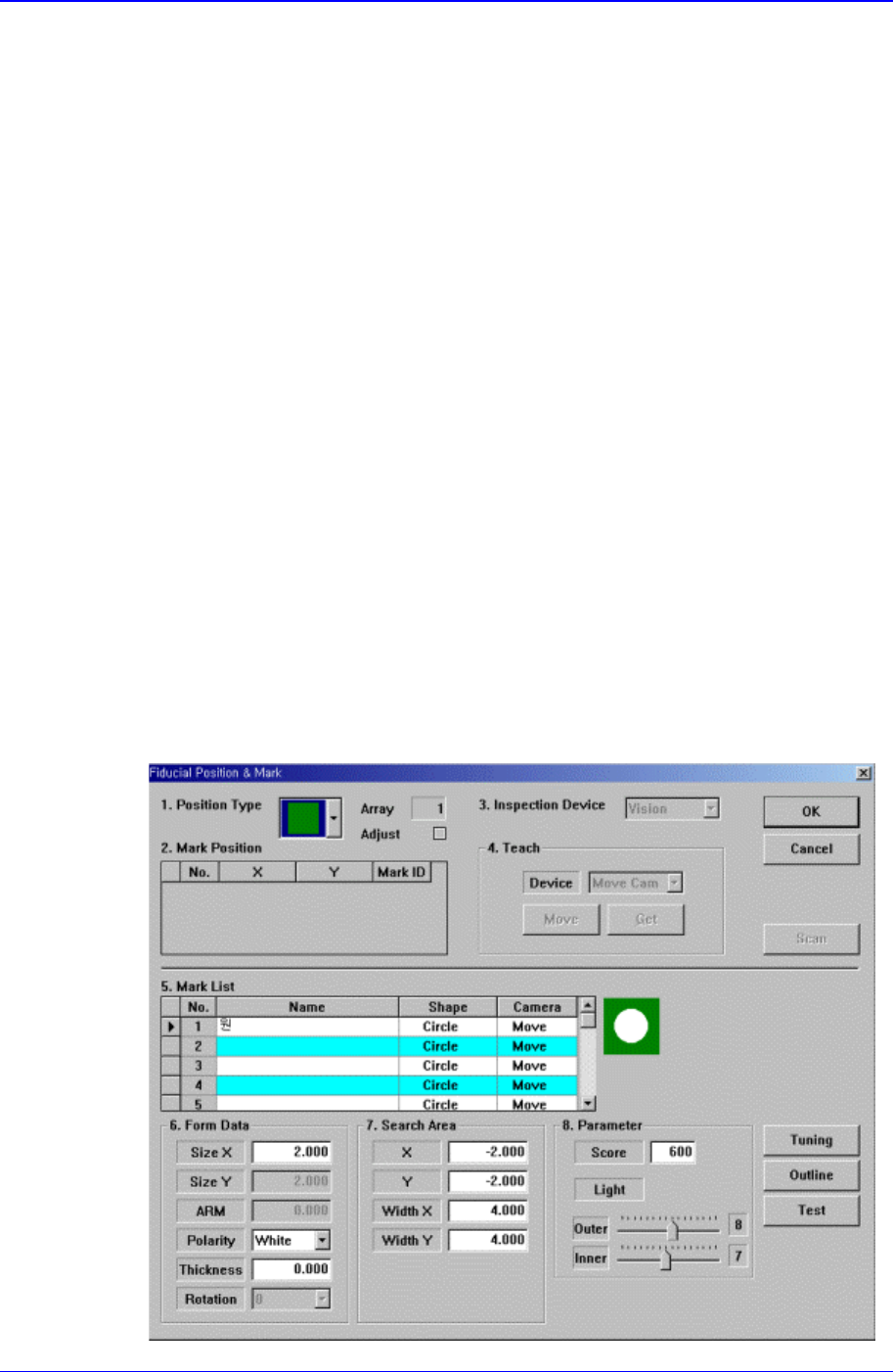
<Fiducial…> button
If the placement point has a fiducial mark, sets the fiducial mark data. When this
button is clicked on, the following dialog box is displayed.