operation-cp45.pdf - 第227页
PCB Edit Command 1 1-73 Figur e 1 1-45 “ Ball Gap of BGA component-when ther e is a selected ar ea ” dial og box <Create All> button Creates all balls. <Remove All> button Removes all balls. <Create&…

Samsung Component Placer CP-45F(V)/FS Operations Manual
11-72
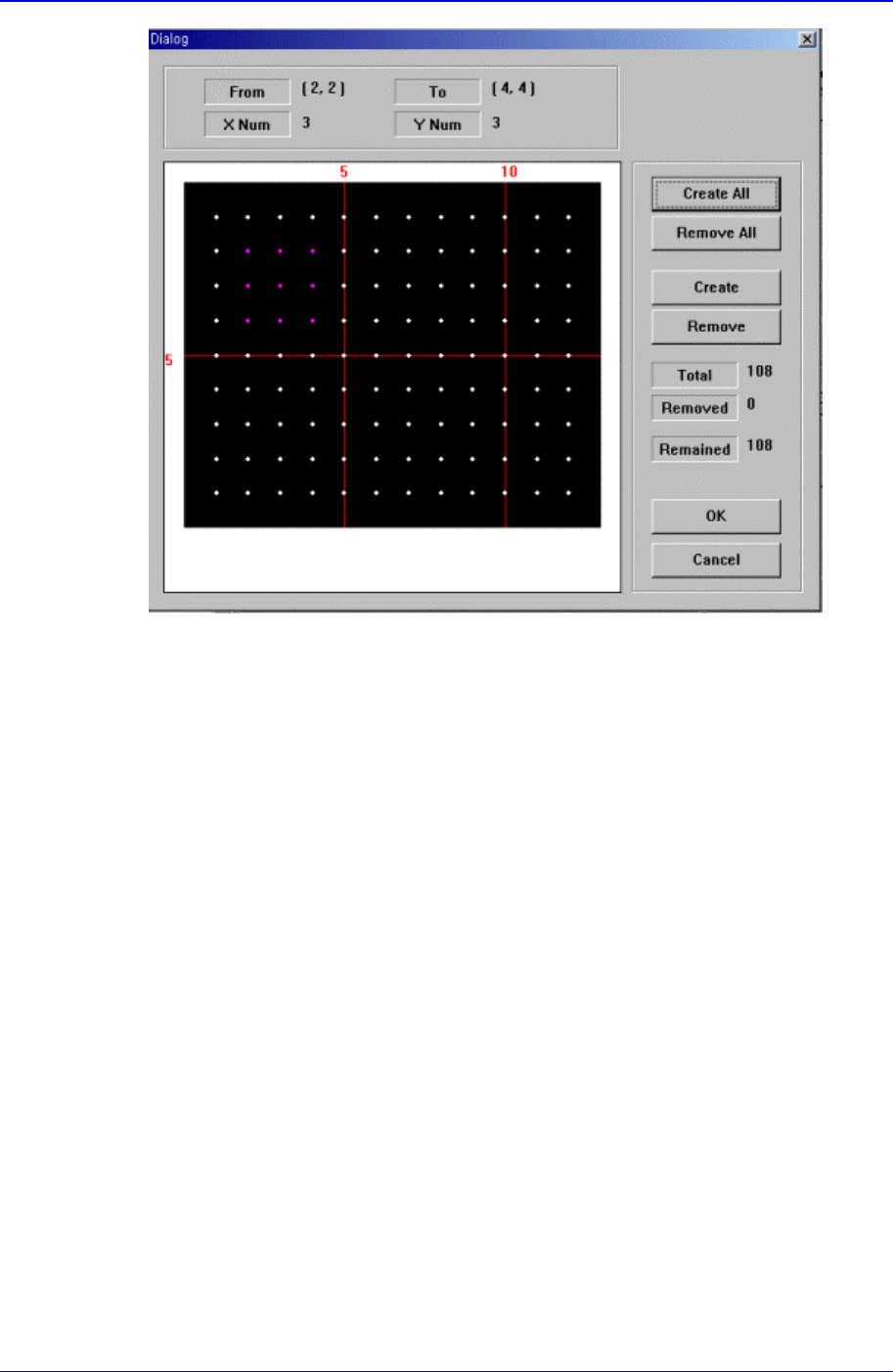
Figure 11-44 “Ball Gap of BGA components-Initial status” dialog box
The grid displays the current ball status. The white dot indicates the ball. To remove
balls in a certain area, the area should be specified first. The area to select can be set
by pressing the left button of the mouse, drag it to the desired area and release it. The
balls in the selected area change color. The following screen shows a case where 25
balls in total, from the ball at (4,4) to the ball at (10,10), 5 balls in X direction and 5
balls in Y direction, are selected.
PCB Edit Command
11-73
Figure 11-45 “Ball Gap of BGA component-when there is a selected area” dialog box
<Create All> button
Creates all balls.
<Remove All> button
Removes all balls.
<Create> button
Creates balls in the selected area.
<Remove> button
Samsung Component Placer CP-45F(V)/FS Operations Manual
11-74
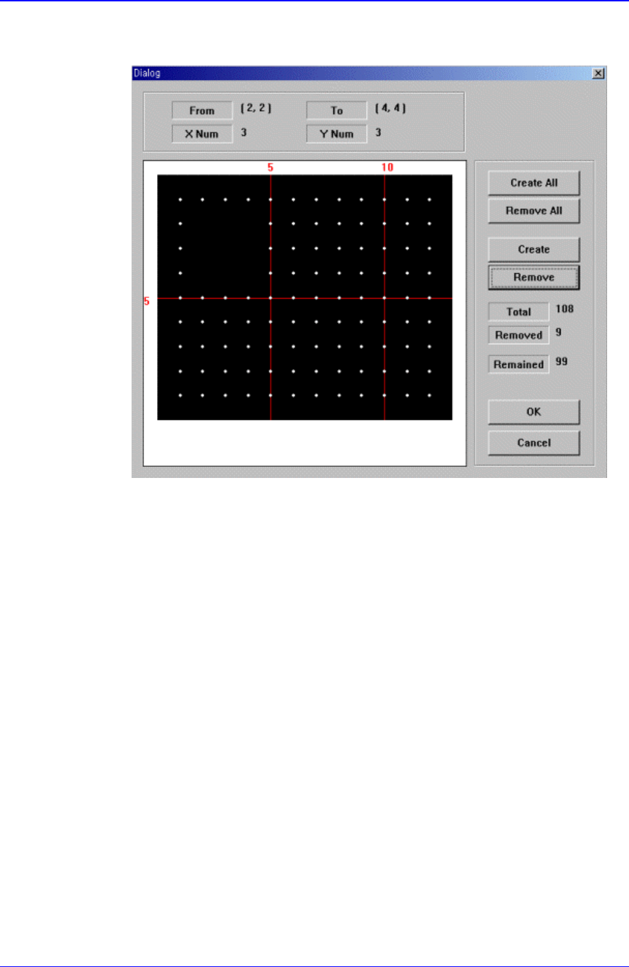
Removes the balls in the selected area.
When the balls in the selected area are removed, the screen looks as follows.
Figure 11-46 “Ball Gap of BGA components-when the balls in the selected area are
removed” dialog box
<OK> button
Saves the set ball gap status and closes the dialog box.
<Cancel> button
Closes the dialog box without saving the set ball gap status.
11.2. Feeder [F4]
The <Feeder> command edits data related to tape feeder, stick feeder, and tray feeder.
The user can specify the part to be installed on each feeder, teach pickups position, and
test component pickups. When this command is selected, the initial screen is for the tape
feeder screen.
11.2.1. Feeder Base
When the feeder base is selected, the following dialog box is displayed and the data on
feeder base can be edited.