operation-cp45.pdf - 第59页
Basic Configuration and Name of Each Part 2-7 2.5.2. Head Specifications T able 2-2. Hea d specification Classification Item Specifications Remarks The number of nozzle 6 Nozzle Head pitch 30 mm Mechanism AC Servo motor …
Samsung Component Placer CP-45F(V)/FS Operations Manual
2-6
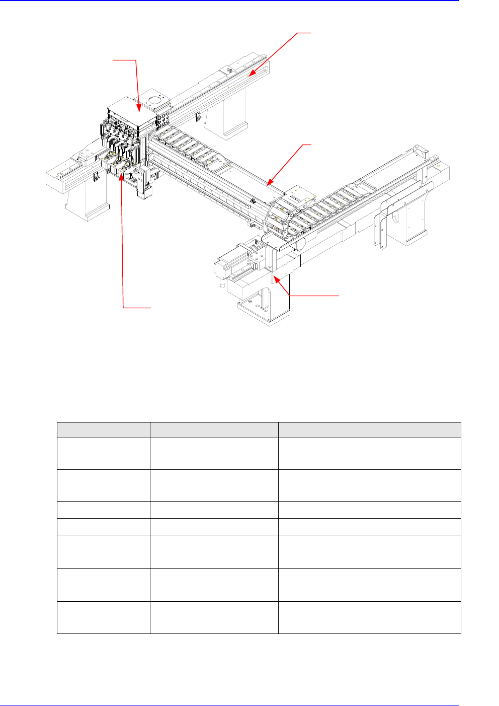
2.5. X-Y Frame Part
Figure 2-6. X-Y Frame Part
2.5.1. XY-Axis Specifications
Table 2-1. XY-Axis specification
Classification Specifications Remarks
Mechanism
X-axis: AC Servo motor
Y-axis: AC Servo motor
400 W
1500 W
Decelerating ratio
X-axis 1:1
Y-axis 1:1
Repeatability
± 0.02 mm
Resolution
5 µm/pulse
X-Axis range
692 mm
682 mm
(+) stopper ↔ (-)stopper
(+) over run sensor ↔ (-)over run sensor
Y-Axis range
916 mm
906 mm
(+) stopper ↔ (-)stopper
(+) over run sensor ↔ (-)over run sensor
The type of
controlling speed
“S” accelerating/
decelerating control
Head Assembly
X Frame
Head I/F Board Cove
r
Y2 Frame
Y1 Frame
Basic Configuration and Name of Each Part
2-7
2.5.2. Head Specifications
Table 2-2. Head specification
Classification Item Specifications Remarks
The number of
nozzle
6 Nozzle
Head pitch 30 mm
Mechanism
AC Servo motor + Belt & LM
+ Compliance Ass'y
Digital control illumination
Movement
range
89.0 mm
85.5 mm
Stopper to stopper
Soft limit sensor
Resolution 0.01 mm/pulse Based on teaching
Z-axis
Repeatability
± 0.02 mm
Under the optimum
conditions
Mechanism
Micro stepping motor +
Belt & Pair
head 1/2, 3/4, 5/6 Pair
Movement
range
Unlimited°
Resolution 0.01 °/pulse Based on teaching
θ -axis
Repeatability
± 0.03 °
Under the optimum
conditions
Head
Recognizant
method
Flying Vision Camera
Upward Vision Camera
ing digital illumination device
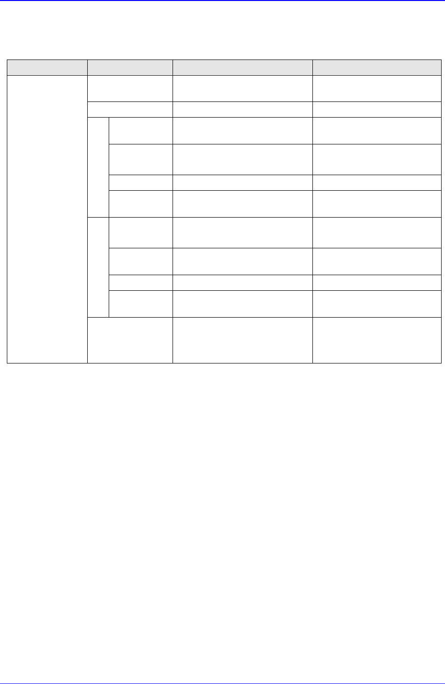
2.6. PCB Conveyor System
2.6.1. Configuration
In the PCB conveyor system, boards from the previous process are transferred, the
placement position is determined, and boards are fixed. This system is divided into three
stages, thus reducing the PCB swap time to the minimum. The flatness of PCB is
improved by affixing the bottom surface of PCB. A wide range of PCB sizes from small-
sized PCB's (30.0mm × 50.00mm) to large-sized PCB's (460.0mm × 400.0mm) can be
accommodated.
The PCB conveyor system configuration is shown below:
Samsung Component Placer CP-45F(V)/FS Operations Manual
2-8
Conveyor
Part
Adjusting
Width Part
Back Up Table
Main Frame
PCB In Belt Ass`y
PCB Working Belt Ass`y
PCB Out Belt Ass`y
Working Stopper
PCB Detect Sensor
Edge Fixer
Auto Width Control Unit
PCB Clamp
Hole Fixer
Figure 2-7. PCB Conveyor System Configuration Diagram
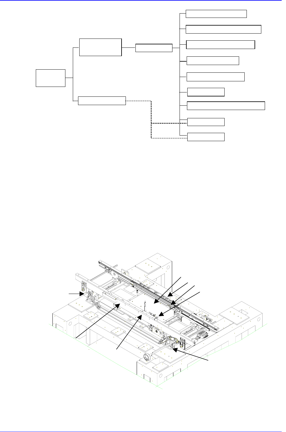
2.6.2. Functions
Functions for each element are as follows.
Main Frame
It is attached on top of the width adjustment part, and serves as the basis of PCB flow.
Various parts are attached to it.
Figure 2-8. PCB Conveyor System Main Frame
Rear frame
Wait stopper
①
②
③
④
①Backup table
②Edge fixer
③PCB detection sensor
④Place stopper
Adjust conveyor
width (L)
Adjust conveyor
width (R)
Out stopper
Hole fixer (R)
Hole fixer (L)
Front frame