operation-cp45.pdf - 第290页
Samsung Component Placer CP-45F(V)/FS Operations Manual 15-4 Figur e 15-4. “ Sys. Setup : System Axis Li mit Info. ” dialog box <Motor Select> group Select the motor axis for which to set the limit. A vailable ax…

Sys.Setup Command
15-3
Set the waiting position for the head block when the PCB is being loaded.
<When Front feeder change button pressed> edit box
When the “Front feeder change” button on the front operation panel of the
equipment is pressed, set the waiting position for the head block.
<When Rear feeder change button pressed> edit box
When the “Rear feeder change” button on the rear operation panel of the
equipment is pressed, set the waiting position for the head block.
<Device> combo box
To move or to read in the position of the XY, and Z axes, select the corresponding
device. Available devices are as follows.
Move Cam: Selects Teaching Camera.
Head1: Selects Head1.
Head2: Selects Head2.
Head3: Selects Head3.
Head4: Selects Head4.
Head5: Selects Head5.
Head6: Selects Head6.
<Move> button
Moves the XY and Z axes to the device selected in <Device>. At this time, the edit
box corresponding to the position to move to must be clicked on with a mouse.
<Get> button
Reads in the current position of XY, and Z axes of the device selected in <Device>.
At this time, the edit box corresponding to the position to be read must be clicked on
with a mouse.
<Update> button
Transmits the set data to the equipment and closes the dialog box.
<Cancel> button
Ignores the set data and closes the dialog box.
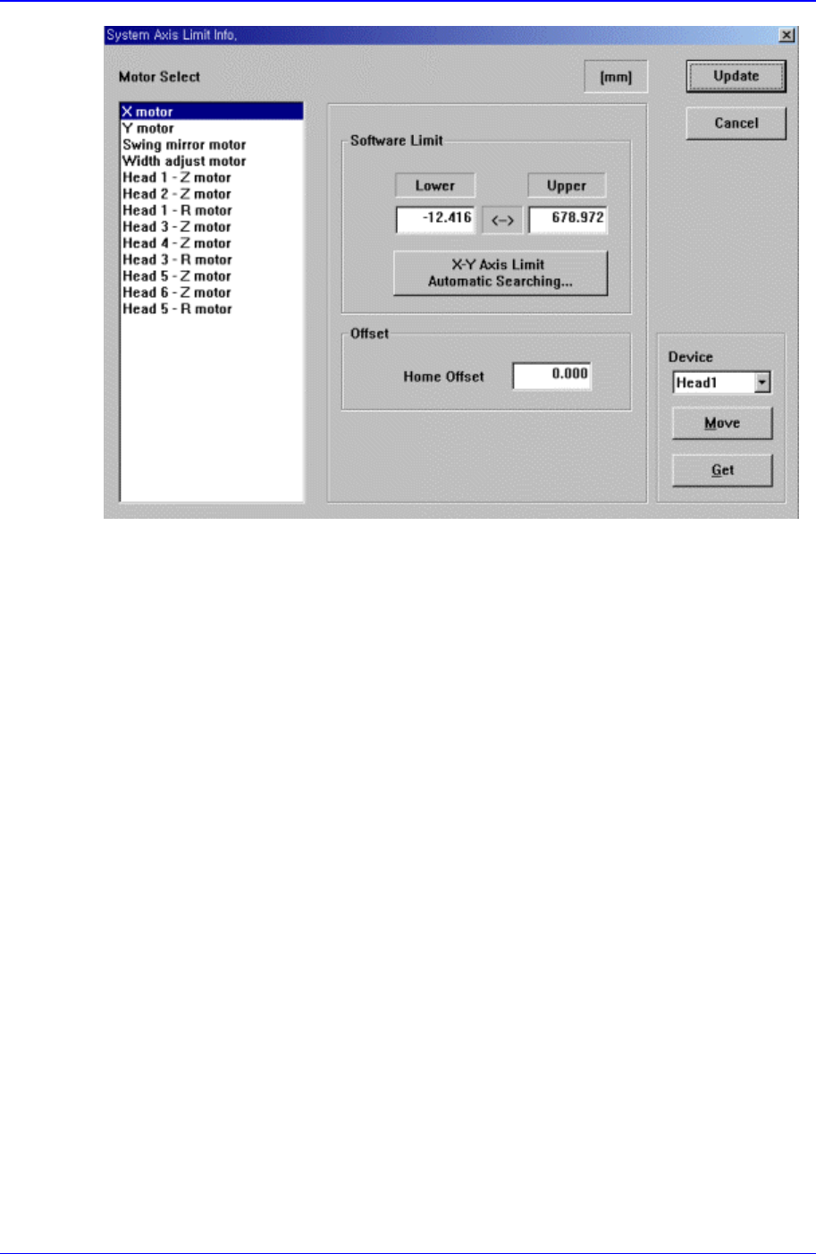
15.2. Limit [F3]
The <Limit> command sets the limit position of each axis to move.
When this button is clicked on, the following dialog box is displayed.
Samsung Component Placer CP-45F(V)/FS Operations Manual
15-4
Figure 15-4. “Sys. Setup : System Axis Limit Info.” dialog box
<Motor Select> group
Select the motor axis for which to set the limit. Available axes are as follows.
X motor: X axis of XY Frame
Y motor: Y axis of XY Frame
Swing mirror motor: Mirror axis of the head block.
Width adjust motor: Width motor axis of conveyor.
Head1 – Z motor: Z axis of Head1
Head2 – Z motor: Z axis of Head2
Head1 – R motor: R axis of Head1
Head3 – Z motor: Z axis of Head3
Head4 – Z motor: Z axis of Head4
Head3 – R motor: R axis of Head3
Head5 – Z motor: Z axis of Head5
Head6 – Z motor: Z axis of Head6
Head5 – R motor: R axis of Head5
<Software Limit> group
Set the limit position of the selected axis.
<Lower> edit box
Set the lower limit position.
<Upper> edit box
Set the upper limit position.
<X-Y Axis Limit Automatic Searching…> button

Sys.Setup Command
15-5
When this button is clicked on, the limit position of the XY axis is searched
automatically.
Caution: Take a precaution since the XY axis moves.
<Offset> group
Set the offset value for the selected axis.
<Home Offset> edit box
Set the offset value when the motor of the selected axis finds Home.
<Device> combo box
To move or to read in the current positions of the XY, and Z axes, select the
corresponding device. Available devices are as follows.
Move Cam: Selects Teaching Camera.
Head1: Selects Head1.
Head2: Selects Head2.
Head3: Selects Head3.
Head4: Selects Head4.
Head5: Selects Head5.
Head6: Selects Head6.
<Move> button
Moves the X,Y, and Z axes to the device selected in <Device>. At this time, the edit
box corresponding to the position to move to must be clicked on with a mouse.
<Get> button
Reads in the current positions of the XY, and Z axes of the device selected in
<Device>. At this time, the edit box corresponding to the position to be read should
be clicked on with a mouse.
<Update> button
Transmits the set data to the equipment and closes the dialog box.
<Cancel> button
Ignores the set data and closes the dialog box.
15.3. Offset [F4]
Sets the offset value between the devices of the head block.
When this button is clicked on, the following dialog box is displayed.