operation-cp45.pdf - 第145页
V iew Commands 9-5 9.1.2. Conveyor Dialog Box Operates the conveyor and the devices attached to the conveyor . Figur e 9-3. “ Manual T ools – Conveyor ” dialog box <Edge Fixture> button Moves backward or forward …
Samsung Component Placer CP-45F(V)/FS Operations Manual
9-4
<Home> button
Moves the axis to the Home position
<for PCB Board Coordinate> group
It is activated when “PCB Array#1” is selected in the <Origin> combo box.
<Part Origin> edit box
Enter the Part Origin of PCB.
<Array Offset> edit box
Enter the origin of Array PCB1.
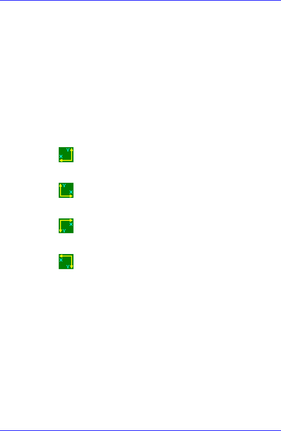
<Coordinate> combo box
Select the PCB coordinate system. Available coordinate systems are as follows.
Left-Up : Based on the front of equipment, it is a coordinate system in
which the X axis increases to the left and the Y axis increases to the top
Right-Up : Based on the front of equipment, it is a coordinate system in
which the X axis increases to the left and the Y axis increases to the top.
Left-Down : Based on the front of equipment, it is a coordinate system in
which the X axis increases to the left and the Y axis increases to the top.
Right-Down : Based on the front of equipment, it is a coordinate system in
which the X axis increases to the left and the Y axis increases to the top.
View Commands
9-5
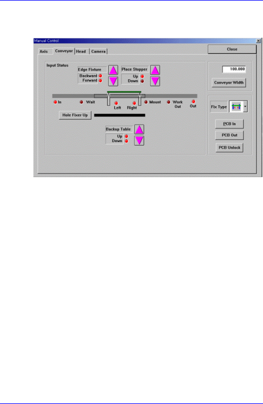
9.1.2. Conveyor Dialog Box
Operates the conveyor and the devices attached to the conveyor.
Figure 9-3. “Manual Tools – Conveyor” dialog box
<Edge Fixture> button
Moves backward or forward the edge fixer.
<Place Stopper> button
Moves up or down the place stopper.
<Backup Table> button
Moves up or down the backup table.
<Hole Fixer Up> button
Moves up the hole fixer.
<Conveyor Width> edit box
Enter the conveyor width.
<Conveyor Width> button
Automatically adjusts the conveyor width to the value entered in the <Conveyor
Width> edit box.
<Fix Type> combo box
Select the PCB arrangement method.

Samsung Component Placer CP-45F(V)/FS Operations Manual
9-6
Hole Fixer: A method of arrangement by inserting pins in the holes of the
PCB.
Edge Fixer: A method of arrangement by pushing the PCB from the side with
a device attached to the conveyor.
Edge Fixer2: It is the same as the “Edge Fixer” method, but it is a method of
arrangement by pushing twice from the side.
<PCB In> button
Loads the PCB in the operation area. Before executing this function, the PCB
arrangement method must be set in <Fix Type>.
<PCB Unlock> button
Releases the PCB fixed in the operation area.
<PCB Out> button
Releases the PCB in the operation area to the next machine.
9.1.3. Head block Dialog Box
Used to turn on/off the air pressure of each head, set the light value of each camera,
open/close the mirror of the head block, and put all nozzles.