operation-cp45.pdf - 第244页
Samsung Component Placer CP-45F(V)/FS Operations Manual 11-90 <X> column Of the 3 components on the tray to be taught, it is the X position of no. 1 corner point of the pocket containing the first component. &l…
PCB Edit Command
11-89
When component pickups fails, set the Z position to dump( At this time, the
dump box should be already set to tray).
<R> column
When a tray feeder is installed on the corresponding tray, set the R
position(rotation angle of the head) to pick up the component supplied from the
tray feeder.
<PartR> column
When a tray feeder is installed on the corresponding tray, set the placement angle
of the component supplied from the tray feeder.
<SK> column
When a tray feeder is installed on the corresponding tray, select whether to pick
up the component supplied from the tray feeder or not.
To pick up the component, leave the check box as it is, and not to pick up the
component, check the check box.
<Dump> column
When a tray feeder is installed on the corresponding tray, select the dump box for
the component supplied from the tray feeder. Available dump boxes are as
follows.
Return to Tray: Dumps to the tray from which the component was picked up.
User Dump: Sets the dump box set by the user in the system..
The method of setting the pickups position for the component installed on the
tray is explained next. Unlike the tape or stick, the same type of components are
regularly arranged on the tray. Therefore, instead of setting all component
pickups points, pickups points for several components are set and the rest are
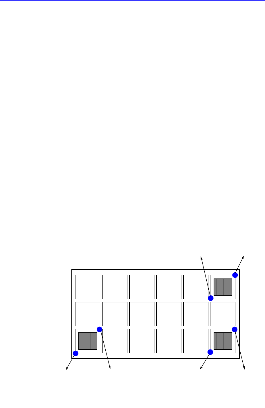
calculated automatically. In this equipment, as shown below, 2 points each on 3
components are taught and the pickups points are obtained.
Pocket
1
Pocket
2
Pocket
3
Point1-1 Point1-2 Point2-2Point2-1
Point3-2Point3-1
<Point1-1> group

Samsung Component Placer CP-45F(V)/FS Operations Manual
11-90
<X> column
Of the 3 components on the tray to be taught, it is the X position of no. 1
corner point of the pocket containing the first component.
<Y> column
Of the 3 components on the tray to be taught, it is the Y position of no. 1
corner point of the pocket containing the first component.
<Point1-2> group
<X> column
Of the 3 components on the tray to be taught, it is the X position of no.2
corner point of the pocket containing the first component.
<Y> column
Of the 3 components on the tray to be taught, it is the Y position of no.2
corner point of the pocket containing the first component.
<Point2-1> group
<X> column
Of the 3 components on the tray to be taught, it is the X position of no.1
corner point of the pocket containing the second component.
<Y> column
Of the 3 components on the tray to be taught, it is the Y position of no.1
corner point of the pocket containing the second component.
<Point2-2> group
<X> column
Of the 3 components on the tray to be taught, it is the X position of no.2
corner point of the pocket containing the second component.
<Y> column
Of the 3 components on the tray to be taught, it is the Y position of no.2
corner point of the pocket containing the second component.
<Point3-1> group
<X> column
Of the 3 components on the tray to be taught, it is the X position of no.1
corner point of the pocket containing the third component.
<Y> column
Of the 3 components on the tray to be taught, it is the Y position of no.1
corner point of the pocket containing the third component.
<Point3-2> group
<X> column
Of the 3 components on the tray to be taught, it is the X position of no.2
corner point of the pocket containing the third component.
<Y> column
Of the 3 components on the tray to be taught, it is the Y position of no.2
corner point of the pocket containing the third component.
<Pick> button
Executes component pickups from the tray feeder installed on the current line in the
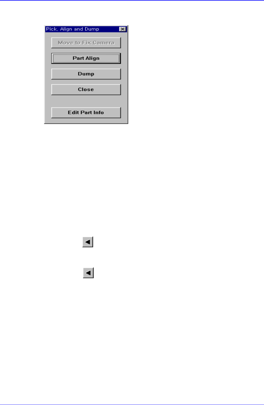
PCB Edit Command
11-91
grid. At this time, the device must be selected first. When pickups is successful, the
following dialog box is displayed.
<Move to Fix Camera> button
It is activated only when the corresponding component is aligned by the vision
camera and the alignment camera is the fix camera. When this button is clicked
on, the head block is moved to the fix camera.
<Part Align> button
Executes alignment of the corresponding component.
<Dump> button
Dumps the corresponding component to the specified dump box.
<Close> button
Closes the dialog box.
<Pocket Move> button
Moves the selected device to the pocket number set in <Current Pocket>.
<Move Prev>
button
Moves the selected device to the pocket number previous to the number set in
<Current Pocket>.
<Move Next>
button
Moves the selected device to the pocket number next to the number set in <Current
Pocket>.
<Current Pocket> group
<X>: Set the pocket number of the tray to move to or pick up from in X direction.
<Y>: Set the pocket number of the tray to move to or pick up from in Y direction.
<Pallet In> button
Loads the pallet to be ready for placement from the elevator of the tray feeder.
<Pallet Out> button
Release the pallet to be finished placement from the elevator of the tray feeder.
<Device> combo box
To move or to read in the position of the XY axis, select the corresponding device.
Available devices are as follows.