operation-cp45.pdf - 第73页
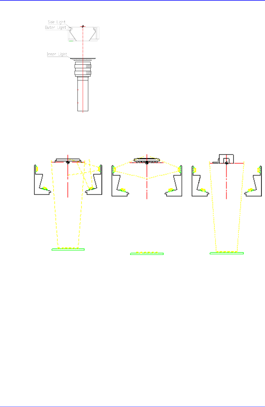
Basic Configuration and Name of Each Part 2-21 Figur e 2-15. Light Path Contr ol The optimum lighting direction for each com ponent is shown in Figure 2-16. Ge ne r a l C om p one nt C B G A C onne c t or s Figur e 2-16.…
Samsung Component Placer CP-45F(V)/FS Operations Manual
2-20
On or Off.
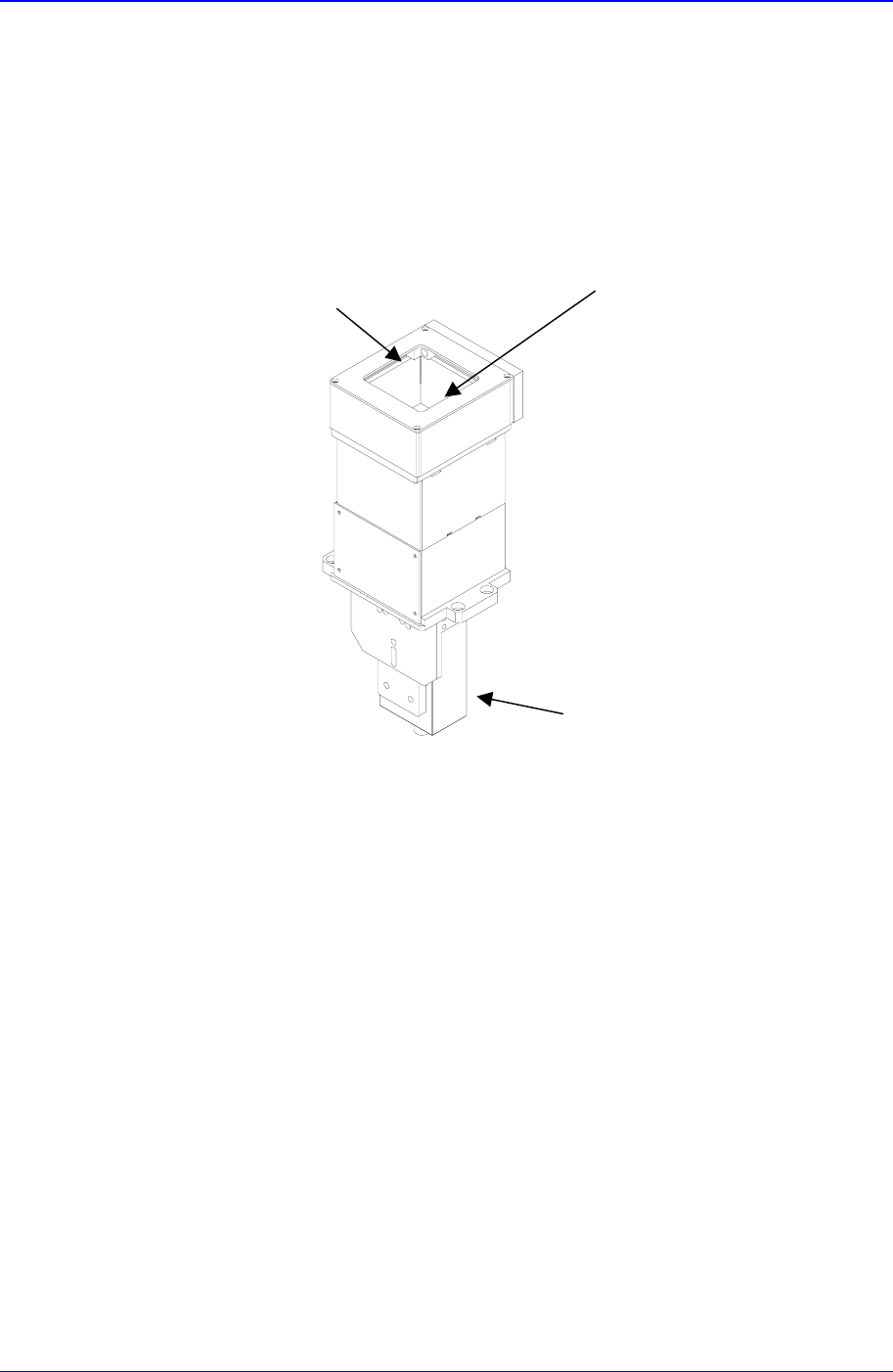
2.10.2. Upward vision unit(For CP-45FV)
The upward vision unit of the CP-45FV model can recognize the general and Odd-type
components, and also has a digital lighting controller. Thus, safe and accurate recognition
and placement is possible.
Figure 2-14. Upward Vision Unit
2.10.2.1. Light path control
The optimum lighting conditions are achieved by selecting the lighting in the desired
direction according to the component to be measured as shown in “Figure 2-15“.
Cover Glass
LED
Camera
Basic Configuration and Name of Each Part
2-21
Figure 2-15. Light Path Control
The optimum lighting direction for each component is shown in Figure 2-16.
General Com
p
onent CBGA Connectors
Figure 2-16. Optimum Lighting Direction for Each Component
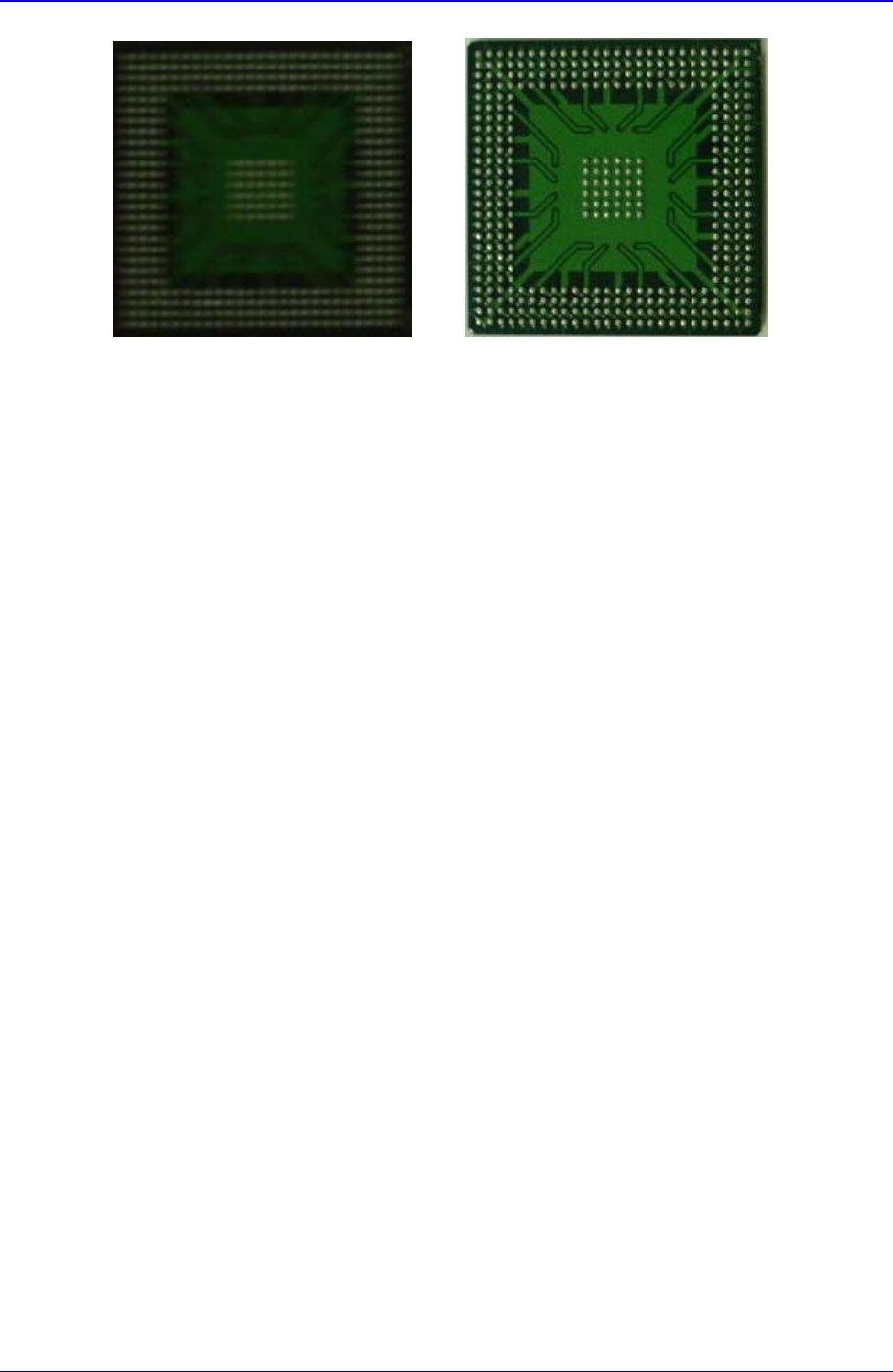
The 3-stage lighting is applied to CBGA process as shown below:
Samsung Component Placer CP-45F(V)/FS Operations Manual
2-22
Figure 2-17. Lighting Application for CBGA Process (Left: general; Right: 3-stage lighting)
As shown in “Figure 2-17“, the exact shape of a ball can be recognized by using the side
lighting.
2.10.2.2. Installation method
It can be installed on the rear feeder base.