operation-cp45.pdf - 第202页
Samsung Component Placer CP-45F(V)/FS Operations Manual 11-48 Displays the binary image of the component on the vision monitor screen. <Option> group Set the align option data. <T olerance H> edit box Set…
PCB Edit Command
11-47
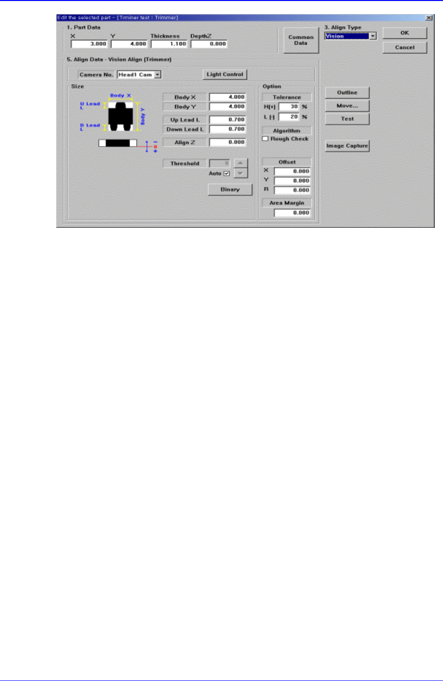
Figure 11-31 “Align Type = Vision, Package Group = Trimmer” dialog box
<Camera No.> combo box
Select the camera to recognize the component.
<Light Control> button
Set the light for the camera to recognize the component.
<Size> group
Set the align size
<Body X> edit box
Set the component size in X direction.
<Body Y> edit box
Set the component size in Y direction.
<Up Lead L> edit box
Set the length of the upper lead in Y direction
<Down Lead L> edit box
Set the length of the lower lead in Y direction
<Align Z> edit box
Set the height for recognition. Based on the component surface, if the top is to be
recognized, set - value and if the bottom is to be recognized, set + value.
<Threshold> edit box
When there is a pre-treatment process for component recognition and the gray
level image is converted into binary, it is the value used as the criteria to
determine black and white.
The value range is 0 – 255(0: black, 255: white), and this value serves to
differentiate the component from the background. When the set value is 0, the
value is set automatically during component recognition.
<Auto> check box
Check it if the <Threshold> value is set automatically.
<Binary> button

Samsung Component Placer CP-45F(V)/FS Operations Manual
11-48
Displays the binary image of the component on the vision monitor screen.
<Option> group
Set the align option data.
<Tolerance H> edit box
Set the highest tolerance for component recognition with a percentage.
<Tolerance L> edit box
Set the lowest tolerance for component recognition with a percentage.
<Algorithm Rough Check> check box
Check it to recognize roughly for component recognition.
<Offset X> edit box
Set the X offset value to be added when the component is placed (After the
component is recognized, it is the value added after the component placement
point adjustment)
<Offset Y> edit box
Set the Y offset value to be added when the component is placed (After the
component is recognized, it is the value added after the component placement
point adjustment.)
<Offset R> edit box
Set the R offset value added when the component is placed (After the component
is recognized, it is the value added after the component placement point is
adjustment.)
<Outline> button
Displays the outline of the component on the vision monitor by using the set align
data.
<Move…> button
Performs component pickups or moves to the fix camera.
<Test> button
Tests component recognition by using the set align data.
11.1.6. Hemt component data setting
Set the align data for Hemt components.
Please refer to “Setting User IC component data”.
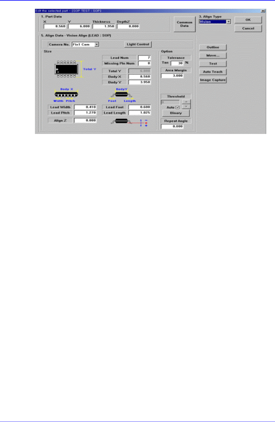
11.1.7. SOP component data setting
Set the align data for SOP components.
PCB Edit Command
11-49
Figure 11-32 “Align Type = Vision, Package Group = SOP” dialog box
<Camera No.> combo box
Select the camera to recognize the component.
<Light Control> button
Select the light for the camera to recognize the component.
<Size> group
Set the align size.
<Lead Num> edit box
Set the number of leads on a side.
<Missing Pin Num> edit box
Set the number of empty leads at the center of the lead column(group).
<Total Y> edit box
Displays the size of the whole component in Y direction. It is calculated and
displayed when <Body Y> and <Lead Length> are determined. ( <Body Y> +
<Lead Length> * 2)
<Body X> edit box
Set the size of component body in X..
<Body Y> edit box
Set the size of component body in Y.
<Lead Width> edit box
Set the width of lead.
<Lead Pitch> edit box
Set the lead pitch
<Lead Foot> edit box
Set the length of the lead that touches the surface.
<Lead Length> edit box
Set the length of the lead viewed in the Align Camera.
<Align Z> edit box