operation-cp45.pdf - 第266页
Samsung Component Placer CP-45F(V)/FS Operations Manual 12-12 Displays the production a. <Bad Mark Skipped PCB Count> Displays the total number of PCBs skipped because of bad mark indication. <PCB In Count u…
Production Command
12-11
feeder, aligned by the upward camera and placed.
<Upward Error> column
Displays the upward error rate of components picked up from the corresponding
feeder and aligned by the upward camera but failed to be placed.
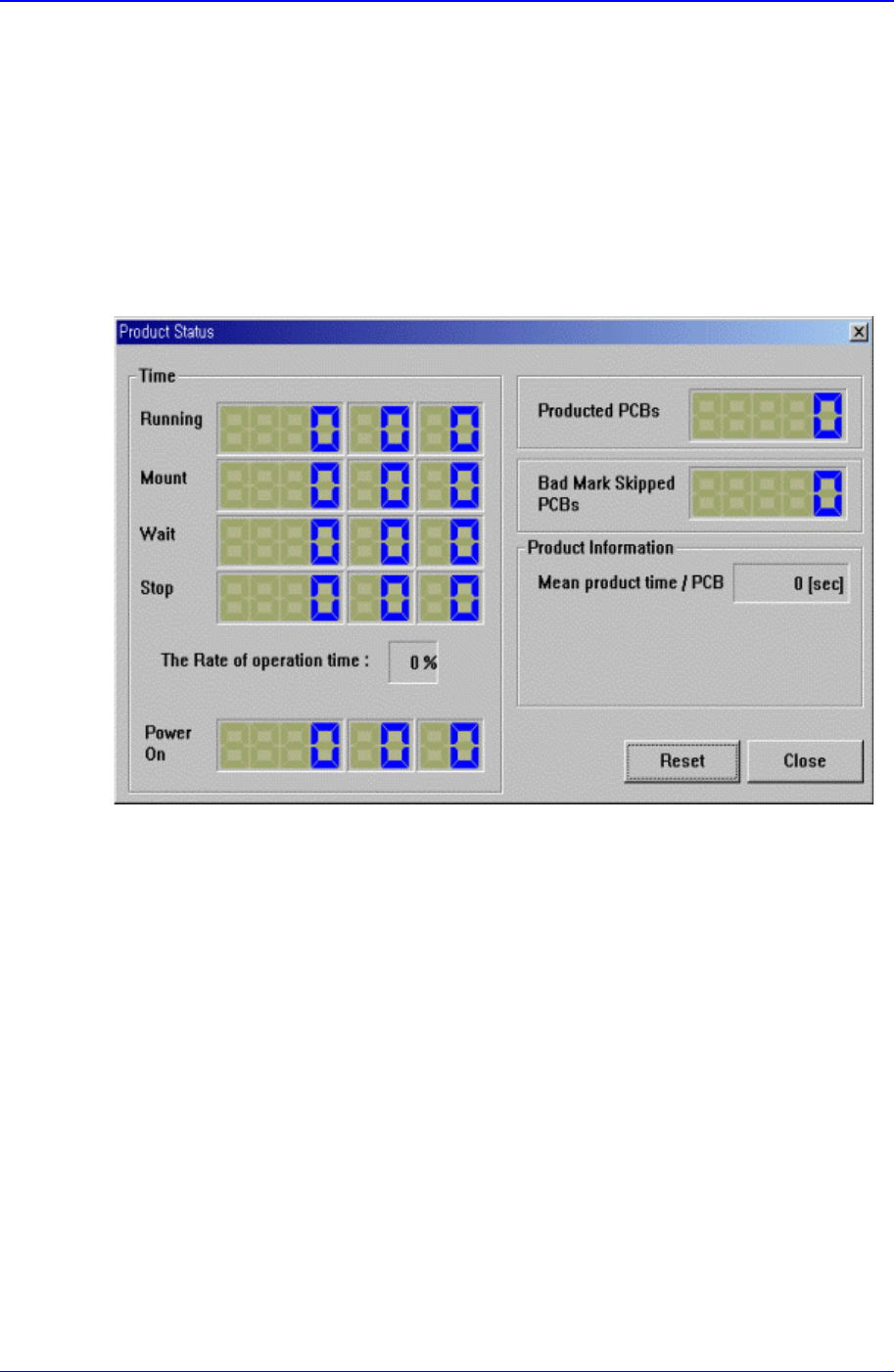
12.9. Sts. Info [F9]
Displays the placement status. When this button is clicked on, the following dialog box is
displayed.
<Time> group
Displays the equipment operation time.
<Elapse> Time
Displays the time elapsed from power supply to the present moment.
<Running> Time
Displays the sum of placement, waiting, and stopping time.
<> Time
Displays the placement time from power supply to the present moment.
<Wait> Time
Displays the time in the waiting status from power supply to the present moment.
<Stop> Time
Displays the time in the stopping status from power supply to the present
moment.
<The Rate of Operation> percentage
Displays the placement time as a percentage of running time.
<Product Information> group

Samsung Component Placer CP-45F(V)/FS Operations Manual
12-12
Displays the production a.
<Bad Mark Skipped PCB Count>
Displays the total number of PCBs skipped because of bad mark indication.
<PCB In Count used for In-Line>
Displays the total number of PCBs loaded on the equipment.
<Fiducial Skip Count>
Displays the total number of PCBs for which the fiducial mark inspection have
been skipped.
<Part Count>
Displays the total number of components placed.
Utility Command
13-1
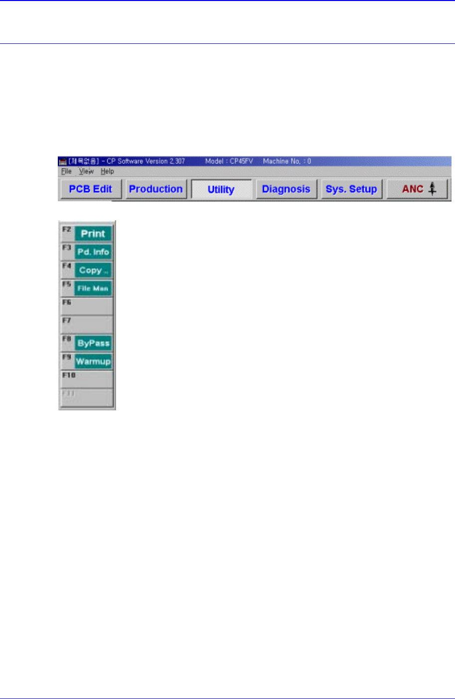
Chapter 13. Utility Command
The utility command is composed of 6 submenus: Print, Production Information, Copy
Between PCB Files, File Manager, Bypass, and Warmup.
This command provides convenience of operation and provides product information
when the machine is started.
When a submenu of the <Utility> command is selected, the corresponding dialog box is
displayed on the screen. While the dialog box corresponding to the submenu is displayed,
selecting the menu again activates the corresponding dialog box.
Figure 13-1. When the Utility command is selected
Figure 13-2. Submenus of the Utility command
13.1. Print... [F2]
The <Print...> command is used to print PCB files. When this command is selected, the
following dialog box is displayed.