operation-cp45.pdf - 第144页
Samsung Component Placer CP-45F(V)/FS Operations Manual 9-4 <Home> button Moves the axis to the Home position <for PCB Board Coordinate> group It is activated when “ PCB Array#1 ” is selected in the <O…

View Commands
9-3
Select the speed level for axis transfer.
Available speed levels are as follows.
1: Selects the fastest level of speed. (Fastest)
2: Selects the fast level of speed. (Fast)
3: Selects the middle level of speed. (Middle)
4: Selects the slow level of speed. (Slow)
5: Selects the slowest level of speed. (Slowest)
<Position> group
To move the axis or to read in the position of the current axis, display the position
value. The displayed position value differs according to the axis selected in <Axis>.
The position values are as follows.
X: The position value of X axis
Y: The position value of Y axis
<Origin> combobox
To move or to read in the current position of the axis, select the origin. Available
origins are as follows.
Machine Logical: Selects the origin of the equipment as the origin.
FeederBase Front (1): Selects the origin of the front feeder base as the origin.
FeederBase Rear (2): Selects the origin of the rear feeder base as the origin.
PCB Bad Mark: Selects the bad mark of the PCB as the origin.
PCB Array#1: Selects the origin of the Array PCB1 as the origin.
Tray Feeder #1: Selects the origin of the Tray Feeder1 as the origin.
Tray Feeder #2: Selects the origin of Tray Feeder2 as the origin.
ANC#1: Selects the origin of ANC1 as the origin.
ANC#2: Selects the origin of ANC2 as the origin.
<Message>
Displays the information generated during the manipulation of axis.
<Move> button
Moves the axis to the value specified in the <Position> group.
<Get> button
Reads in the position of the current axis and displays it in the <Position> group.
Samsung Component Placer CP-45F(V)/FS Operations Manual
9-4
<Home> button
Moves the axis to the Home position
<for PCB Board Coordinate> group
It is activated when “PCB Array#1” is selected in the <Origin> combo box.
<Part Origin> edit box
Enter the Part Origin of PCB.
<Array Offset> edit box
Enter the origin of Array PCB1.
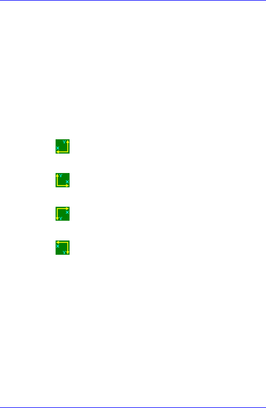
<Coordinate> combo box
Select the PCB coordinate system. Available coordinate systems are as follows.
Left-Up : Based on the front of equipment, it is a coordinate system in
which the X axis increases to the left and the Y axis increases to the top
Right-Up : Based on the front of equipment, it is a coordinate system in
which the X axis increases to the left and the Y axis increases to the top.
Left-Down : Based on the front of equipment, it is a coordinate system in
which the X axis increases to the left and the Y axis increases to the top.
Right-Down : Based on the front of equipment, it is a coordinate system in
which the X axis increases to the left and the Y axis increases to the top.
View Commands
9-5
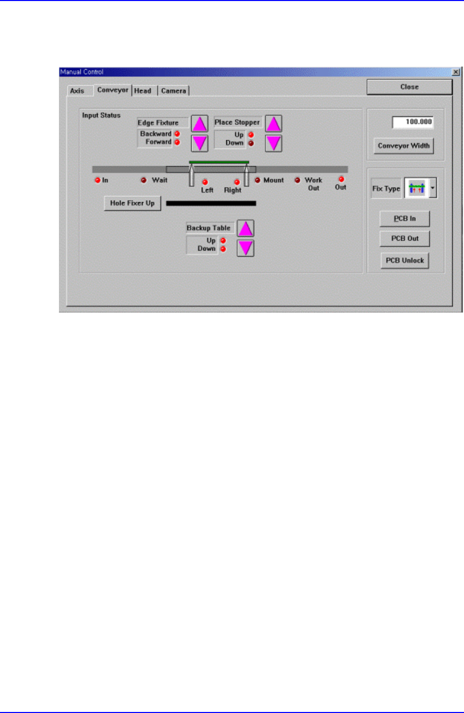
9.1.2. Conveyor Dialog Box
Operates the conveyor and the devices attached to the conveyor.
Figure 9-3. “Manual Tools – Conveyor” dialog box
<Edge Fixture> button
Moves backward or forward the edge fixer.
<Place Stopper> button
Moves up or down the place stopper.
<Backup Table> button
Moves up or down the backup table.
<Hole Fixer Up> button
Moves up the hole fixer.
<Conveyor Width> edit box
Enter the conveyor width.
<Conveyor Width> button
Automatically adjusts the conveyor width to the value entered in the <Conveyor
Width> edit box.
<Fix Type> combo box
Select the PCB arrangement method.