operation-cp45.pdf - 第23页
T able of Contents xv T able of Contents Main Contents Preface ................................................................................................... i About Sa fety .........................................…
Samsung Component Placer CP-45F(V)/FS Operations Manual
xiv
Screen display
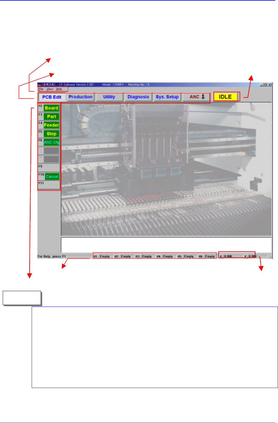
The main screen of MMI of this equipment is shown below:
Pictures showing a dialog box or message box of MMI are inserted to produce this
manual. Therefore, the screens shown in the manual and various settings, values and
contents included within may vary depending on the machine installed or the operational
environment. The MMI screens shown in the manual are inserted for more detailed
reference and explanation. They are produced by enlarging or reducing the contents
appearing on the main screen of MMI.
In addition, pictures inserted in this manual are prepared based on the CP-45FV model,
and therefore, some discrepancies may exist depending on the model.
Memo
The states of nozzles ed on each head are indicated.
X, Y coordinates of the head
position based on head1 are
indicated.
A main menu tool-bar is shown.
Use a menu bar as in a general window
application program
A help message applicable to the
present state as well as the state
of the equipment (IDLE, RUN,
FREEZE, WAIT, PAUSE) is
indicated.
A sub menu tool-bar is shown.

Table of Contents
xv
Table of Contents
Main Contents
Preface ................................................................................................... i
About Safety.................................................................................................... ii
Safety Precaution ............................................................................................iii
About Warranty................................................................................................ix
About This Manual........................................................................................... x
Table of Contents .................................................................................................xv
Main Contents.................................................................................................xv
List of Figures................................................................................................xxi
List of Tables ..............................................................................................xxvii
Overview
Chapter 1. Features and Scope of Equipment..................................................1-1
1.1 Features of Equipment....................................................................1-1
1.1.1.
Features of CP-45F/V AND CP-45FS model....................................1-1
1.2. Applicable Components and Packages ..........................................1-3
1.2.1.
Configuration of the head and vision recognition system.................1-3
1.2.2. Applicable component sizes.............................................................1-3
1.2.3. The placement precision...................................................................1-4
1.2.4. The pick & place cycle time..............................................................1-4
1.3. Mechanical Specifications...............................................................1-7
1.3.1.
Size and weight of the equipment.....................................................1-7
1.3.2. Requirements for air pressure..........................................................1-7
1.3.3. Environmental conditions..................................................................1-7
1.3.4. Noise.................................................................................................1-8
1.4. Electrical Specifications ..................................................................1-8
1.4.1.
Power requirements..........................................................................1-8
1.4.2. EPU (External Programming Unit)....................................................1-9
1.4.3. HLC (Host Line Computer)...............................................................1-9
1.5. Control System Specifications ......................................................1-11

Samsung Component Placer CP-45F(V)/FS Operations Manual
xvi
1.5.1.
PCB production..............................................................................1-11
1.5.2. Creation and editing of production program...................................1-12
1.5.3. Input/Output device........................................................................ 1-12
1.5.4. Number of data that can be handled by MMI................................. 1-13
1.5.5. Connections with peripheral units..................................................1-14
Chapter 2. Basic Configuration and Name of Each Part .................................. 2-1
2.1. Exterior (Name of Each Part) ......................................................... 2-1
2.2. System Configuration..................................................................... 2-2
2.2.1.
Mechanical part configuration..........................................................2-2
2.2.2. Control part configuration.................................................................2-3
2.3. Head Assembly.............................................................................. 2-4
2.3.1.
Head assembly of CP-45F/V and CP-45FS.....................................2-4
2.4. Coordinate System......................................................................... 2-5
2.4.1.
X, Y-axis...........................................................................................2-5
2.4.2. Z-axis............................................................................................... 2-5
2.4.3. Theta (R)-Axis.................................................................................. 2-5
2.5. X-Y Frame Part .............................................................................. 2-6
2.5.1.
XY-Axis Specifications..................................................................... 2-6
2.5.2. Head Specifications......................................................................... 2-7
2.6. PCB Conveyor System................................................................... 2-7
2.6.1.
Configuration....................................................................................2-7
2.6.2. Functions ......................................................................................... 2-8
2.7. Board Specifications..................................................................... 2-11
2.7.1.
PCB sizes, allowable deflection error.............................................2-11
2.7.2. PCB conveyor system height......................................................... 2-12
2.7.3. Conveyor rail width controller......................................................... 2-12
2.7.4. Conveyor Regulator Pressure Setting ...........................................2-12
2.7.5. Conditions for PCB ........................................................................2-13
2.8. Detection of Improper Component Pickups.................................. 2-14
2.9. PCB Coordinate Correction Function (Fiducial Mark Recognition)2-14
2.9.1.
Fiducial inspection .........................................................................2-15
2.10. Component Alignment Method (Component Centering Method).. 2-17
2.10.1.
Flying Vision...................................................................................2-17
2.10.2. Upward vision unit(For CP-45FV)..................................................2-20