operation-cp45.pdf - 第199页
PCB Edit Command 1 1-45 <Camera No.> combo box Select the camera to recognize the component. <Light Control> button Set the light for the camera to recognize the component. <Size> group Set the Al…
Samsung Component Placer CP-45F(V)/FS Operations Manual
11-44
Set align option data.
<Tolerance H> edit box
Set the highest tolerance for component recognition with a percentage.
<Tolerance L> edit box
Set the lowest tolerance for component recognition with a percentage.
<Offset X> edit box
Set the X offset value to be added when the component is placed. (After the
component is recognized, it is the value added after the component placement
point adjustment)
<Offset Y> edit box
Set the Y offset value to be added when the component is placed. (After the
component is recognized, it is the value added after the component placement
point adjustment.)
<Offset R> edit box
Set the R offset value to be added when the component is placed. (After the
component is recognized, it is the value added after the component placement
point adjustment).
<Outline> button
Displays the outline of the component on the vision monitor by using the set align
data.
<Move…> button
Performs component pickups or moves to the fix camera.
<Test> button
Tests component recognition by using the set align data.
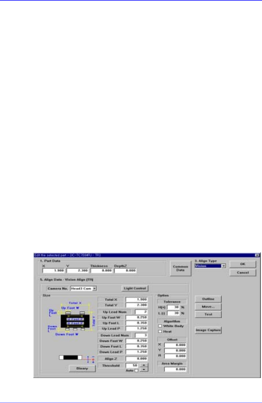
11.1.4. TR component data setting
Set the align data for TR components.
Figure 11-30. “Align Type = Vision, Package Group = TR” dialog box

PCB Edit Command
11-45
<Camera No.> combo box
Select the camera to recognize the component.
<Light Control> button
Set the light for the camera to recognize the component.
<Size> group
Set the Align size.
<Body X> edit box
Set the component size in X direction.
<Body Y> edit box
Set the component size in Y direction.
<Up Lead Num> edit box
Set the number of upper leads.
<Up Lead W> edit box
Set the length of the upper lead in X direction.
<Up Lead L> edit box
Set the length of the upper lead in Y direction
<Up Lead P> edit box
Set the pitch between upper leads.
<Down Lead Num> edit box
Set the number of lower leads.
<Down Lead W> edit box
Set the length of lower lead in X direction.
<Down Lead L> edit box
Set the length of lower lead in Y direction.
<Down Lead P> edit box
Set the pitch between lower leads.
<Align Z> edit box
Set the height for recognition. Based on the component surface, if the top is to be
recognized, set - value and if the bottom is to be recognized, set + value.
<Threshold> edit box
When there is a pre-treatment process for component recognition and the gray
level image is converted into binary, it is the value used to determine black and
white.
The value range is 0 – 255(0: black, 255: white), and this value serves to
differentiate the component from the background. When the set value is 0, the
value is set automatically during component recognition.
<Auto> check box
Check it when the <Threshold> value is set automatically.
<Binary> button
Displays the binary image of the component on the vision monitor screen.
<Option> group

Samsung Component Placer CP-45F(V)/FS Operations Manual
11-46
Set align option data.
<Tolerance H> edit box
Set the highest tolerance for component recognition with a percentage.
<Tolerance L> edit box
Set the lowest tolerance for component recognition with a percentage.
<Algorithm White Body> check box
Check it if the color of the component body is “White Body”.
<Algorithm Heat> check box
Check it if a radiator is attached to the component body.
<Offset X> edit box
Set the X offset value when the component is placed (After the component is
recognized, it is the value added after the component placement point
adjustment.)
<Offset Y> edit box
Set the Y offset value when the component is placed (After the component is
recognized, it is the value added after the component placement point
adjustment)
<Offset R> edit box
Set the R offset value when the component is placed(After the component is
recognized, the value is to be added after the component placement point
adjustment)
<Outline> button
Displays the outline of the component on the vision monitor by using the set align
data.
<Move…> button
Performs component pickups or moves to the fix camera.
<Test> button
Tests component recognition by using the set align data.
11.1.5. Trimmer component data setting
Set align data for Trimmer components.