operation-cp45.pdf - 第178页
Samsung Component Placer CP-45F(V)/FS Operations Manual 11-24 between these data. C huck Ali gn Pa c ka ge QA Ali gn Pa c ka ge CA Al i g n Pa c ka ge Vis i on Align Pa c ka ge C ommon Pa c ka ge Pa rt (Al ign T ype) Fig…

PCB Edit Command
11-23
Set the area to test the Accept Mark. The purpose is to limit the testing area when
recognition is interfered due to a shape similar to the mark near the mark.
<Width X> edit box
Set the range to test in X axis direction. In general, set to 6mm.
<Width Y> edit box
Set the range to test in Y axis direction. In general, set to 6mm.
<8. Parameter> group
<Threshold> edit box
Set the threshold value of <Bad Mark Logic> when testing the Accept Mark.
For example, if <Accept Mark Logic> is “Black” and the <Threshold> value
is 100, all values under 100 in the vision image are recognized as black. And
if <Accept mark Logic> is “White” and the <Threshold> value is 100, all
values over 100 in the vision image are recognized as white. On the vision
display, the image for which the threshold value is applied is in the binary
mode and the image for which the threshold value is not applied is the real
display.
<Light> group
Set the lighting value when testing the Accept Mark. In general, set to 7.
However, adjust it properly according to the condition of the PCB and accept
mark.
<Test> button
Tests the mark by using the set mark data. The user can check whether the set
mark data is correct.
<PCB In> button
Loads the PCB in the operation area.. Before executing this function, the PCB
arrangement method must be set in “Fix Type” of <7. Handling>.
<PCB Out> button
Releases the PCB fixed in the operation area.
<Stopper U/D> button
Moves up or down the work stopper, the stopper of PCB in the operation area.
<BUT U/D> button
Moves up or down the BUT(Back Up Table) that locks up the PCB in the operation
area.
<Cancel> button
Cancels the edited data.
Caution - If you move to another screen while editing the “Board” dialog box, the
edited data is saved automatically.
11.1. Part [F3]
The <Part> command is used to register components necessary for PCB operation and
edit data.
The component data managed by this equipment include PCB Part, Local Part Library,
and Standard Part DB. The following is the structure of each data and the relationship
Samsung Component Placer CP-45F(V)/FS Operations Manual
11-24
between these data.
Chuck Align
Package
QA Align
Package
CA Align
Package
Vision Align
Package
Common
Package
Part
(Align Type)
Figure 11-17. Component Data Structure
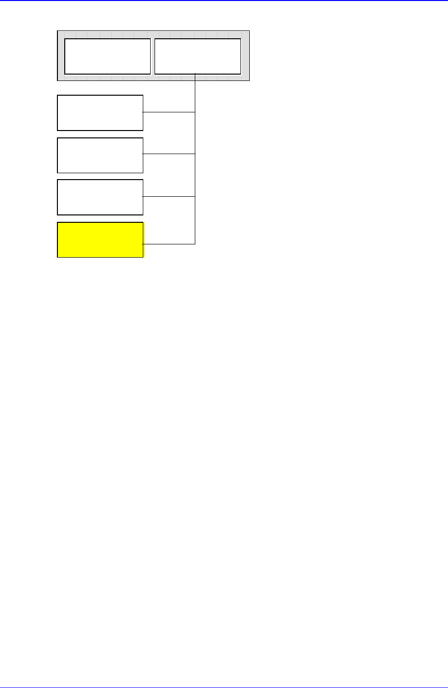
The component data in the Figure 11-19 is composed of “Part” that controls component
names and component sizes and “Common Package” that has the data related to the
machine.
Based on the alignment device, the component alignment methods (hereafter Align Type)
are classified into “Chuck Align”, “QA Align (Quad Aligner)”, “CA Align(Cyber Optics)”,
and “Vision Align”. And as the data controlled differ depending on the align type, the
align data are classified into “Chuck Align Package”, “QA Align Package”, “CA Align
Package”, and “Vision Align Package”.
The align data of a component can have only one or more than one of the four listed
above. Set the align data to be applied now in the Align Type of “Part”.
In the Fig. 1-1, “Vision Align Package” is being set with the current align data.
Each PCB controls component data on all components operated on the corresponding
PCB and saves the component data in the Local Part DB of the equipment. To create
component data for a new PCB, component data stored in the Local Part DB can be
copied. To create component data for a new component whose data is not stored in the
Local Part DB, data for a similar component stored in the Local Part DB can be copied
and edited or standard component data can be copied from the Standard Part DB and
edited. The Standard Part DB is a DB of generally used components developed and
supplied by this equipment manufacturer. The relationship between component data is
shown in the following.
PCB Edit Command
11-25
Standard
Part DB
PCB Part
Local
Part DB
Figure 11-18. Relationship between component DBs
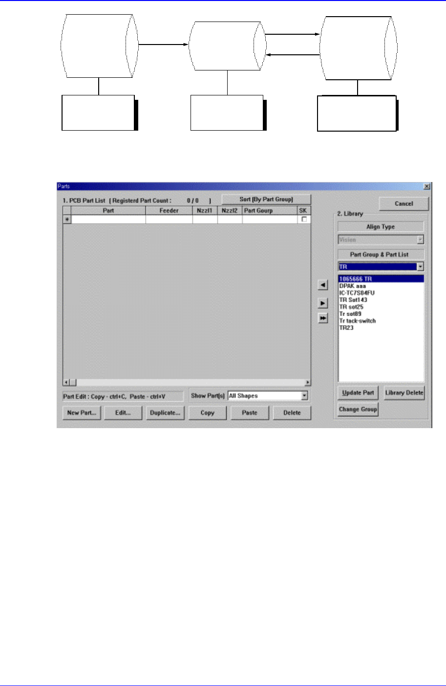
When the <Part> command is selected, the initial screen is as follows.
Figure 11-19.”Parts” dialog box
<1. PCB Part List> group
Display a list of currently registered components.
<Part> column
Displays the component name.
<Feeder> column
Create
New
p
art
Save
Copy
Applied to
all PCBs
Controlled by
each PCB
Controlled by
each equipment