operation-cp45.pdf - 第268页
Samsung Component Placer CP-45F(V)/FS Operations Manual 13-2 Figur e 13-3. “ Print “ dialog box <Cover Data> group Used to enter necessary information when a cover for the output is wanted. Enter the title of the…
Utility Command
13-1
Chapter 13. Utility Command
The utility command is composed of 6 submenus: Print, Production Information, Copy
Between PCB Files, File Manager, Bypass, and Warmup.
This command provides convenience of operation and provides product information
when the machine is started.
When a submenu of the <Utility> command is selected, the corresponding dialog box is
displayed on the screen. While the dialog box corresponding to the submenu is displayed,
selecting the menu again activates the corresponding dialog box.
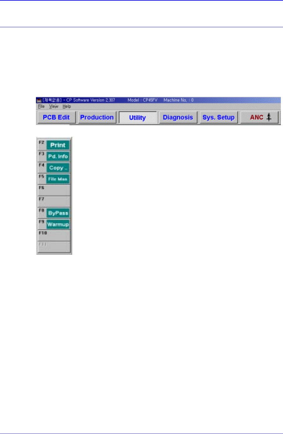
Figure 13-1. When the Utility command is selected
Figure 13-2. Submenus of the Utility command
13.1. Print... [F2]
The <Print...> command is used to print PCB files. When this command is selected, the
following dialog box is displayed.
Samsung Component Placer CP-45F(V)/FS Operations Manual
13-2
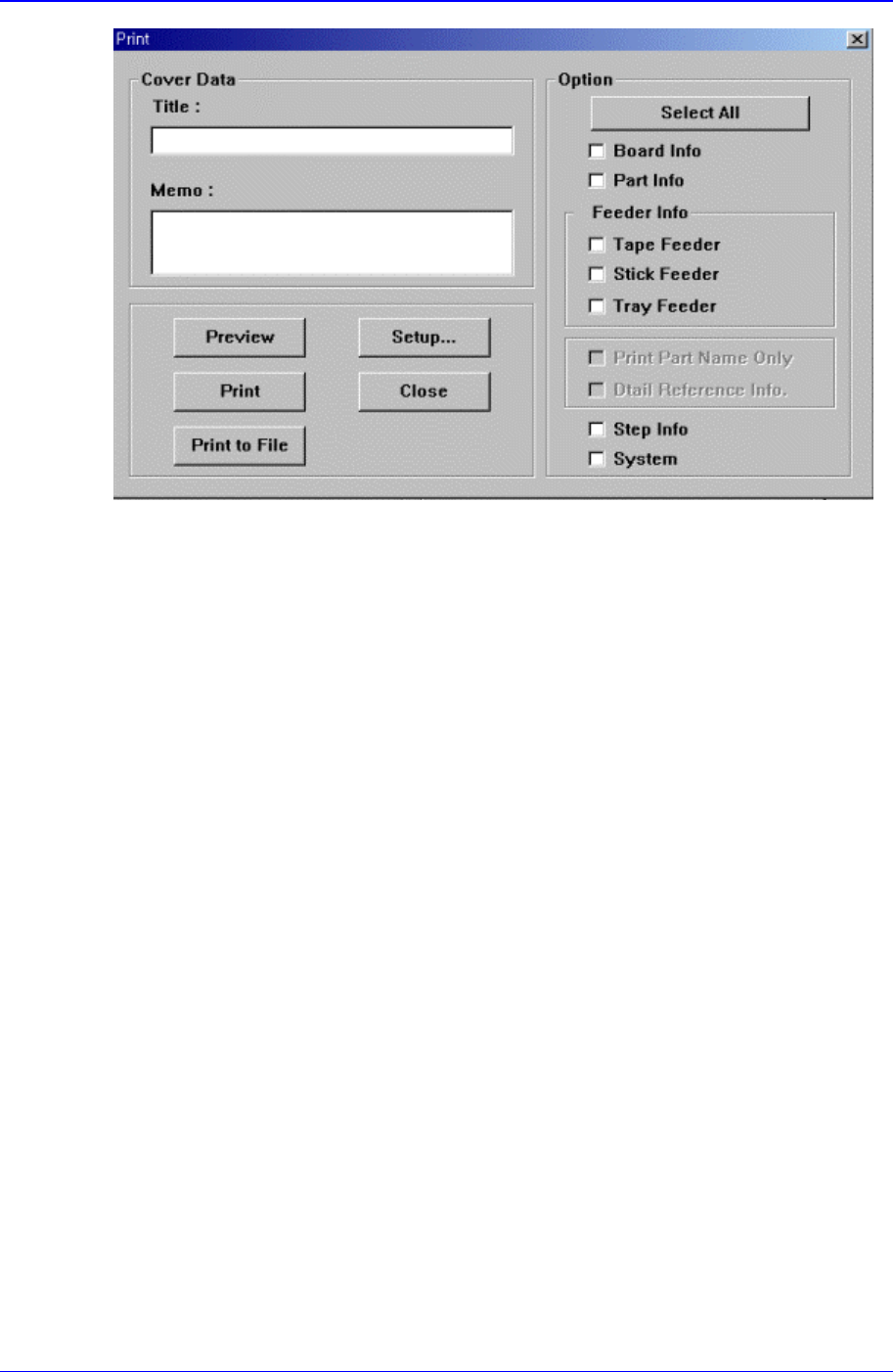
Figure 13-3. “Print “ dialog box
<Cover Data> group
Used to enter necessary information when a cover for the output is wanted. Enter the
title of the output in the “Title” edit box, and enter a short message to be displayed on
the cover in the “Memo” edit box.
<Option> check box group
<Board Info.>check box
Select the information on PCB Boards.
<Part Info.> check box
Select the information on components.
<Feeder Info> check box
Select the information on the feeder to print.
<Step Info.>check box
Select the information on operation sequence.
<System>check box
Select the information on the system parameter of the equipment.
<Preview> button
Displays the content to be printed on the screen first.
<Setup…> button
Sets the printer.
<Print> button
Prints the checked content and closes the “Print “ dialog box.
<Cancel> button
Cancels the execution of <Print> command and closes the “Print “ dialog box.
Utility Command
13-3
13.2. Pd. Info[F3]
Displays the production management data.
13.3. Copy…[F4]
The <Copy data between PCB files> command performs the similar function as
the<Browse> function of the <New> command, but it does not create a new PCB file. A
preexisting file is copied to a designated PCB file.
When the <Copy data between PCB file> command is selected, the following dialog box
is displayed.
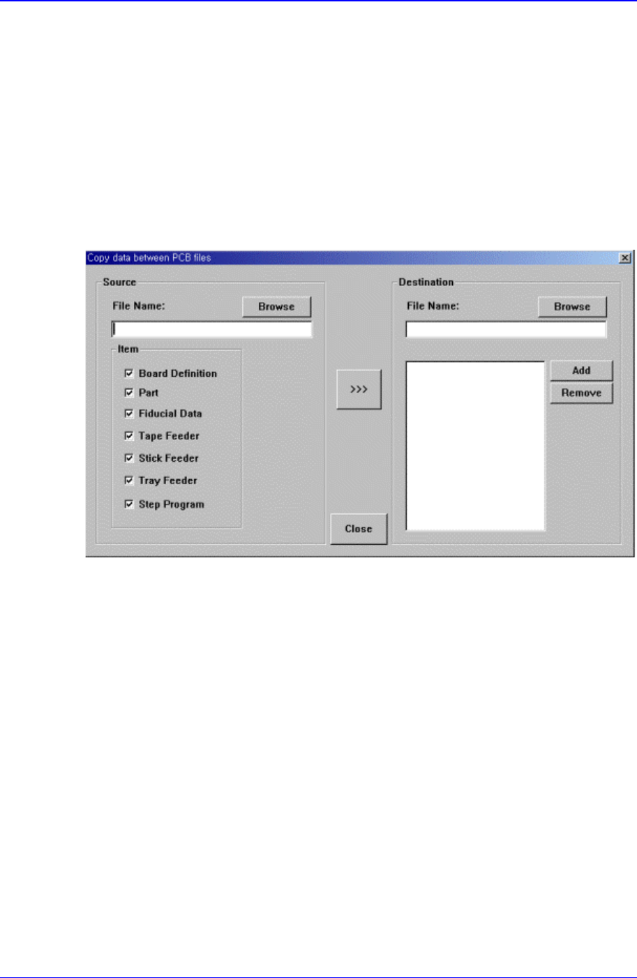
Figure 13-4. “Copy data between PCB files” dialog box
<Source File> edit box
The source file to be copied. The source file name can be selected by entering the
name of the source file directly or by clicking on the <Browse...> button on the right.
<Browse…> button
Displays the location of the source file to be copied. When this button is clicked on,
the following dialog box is displayed.