operation-cp45.pdf - 第74页
Samsung Component Placer CP-45F(V)/FS Operations Manual 2-22 Figur e 2-17. Lighting Application for CBGA Pr ocess (Left: general; Right: 3-stage l ighting) As shown in “ Figur e 2-17 “ , the exact shape of a ball can be …
Basic Configuration and Name of Each Part
2-21
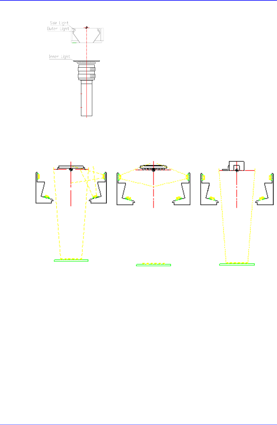
Figure 2-15. Light Path Control
The optimum lighting direction for each component is shown in Figure 2-16.
General Com
p
onent CBGA Connectors
Figure 2-16. Optimum Lighting Direction for Each Component
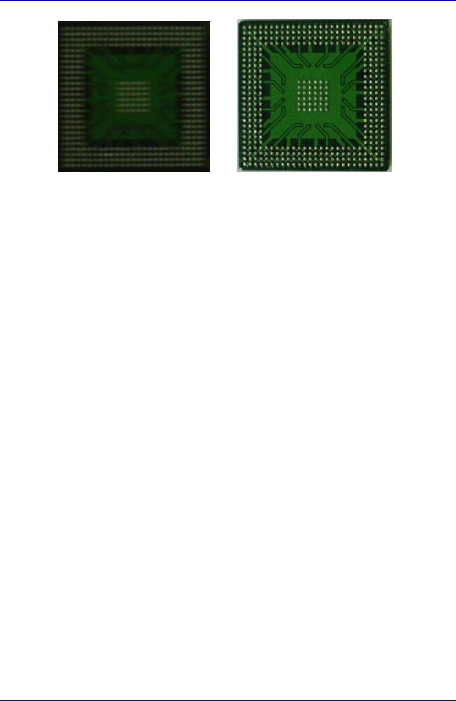
The 3-stage lighting is applied to CBGA process as shown below:
Samsung Component Placer CP-45F(V)/FS Operations Manual
2-22
Figure 2-17. Lighting Application for CBGA Process (Left: general; Right: 3-stage lighting)
As shown in “Figure 2-17“, the exact shape of a ball can be recognized by using the side
lighting.
2.10.2.2. Installation method
It can be installed on the rear feeder base.
Basic Configuration and Name of Each Part
2-23
2.11. Component Alignment Method (Centering Method) and Component
Relationships
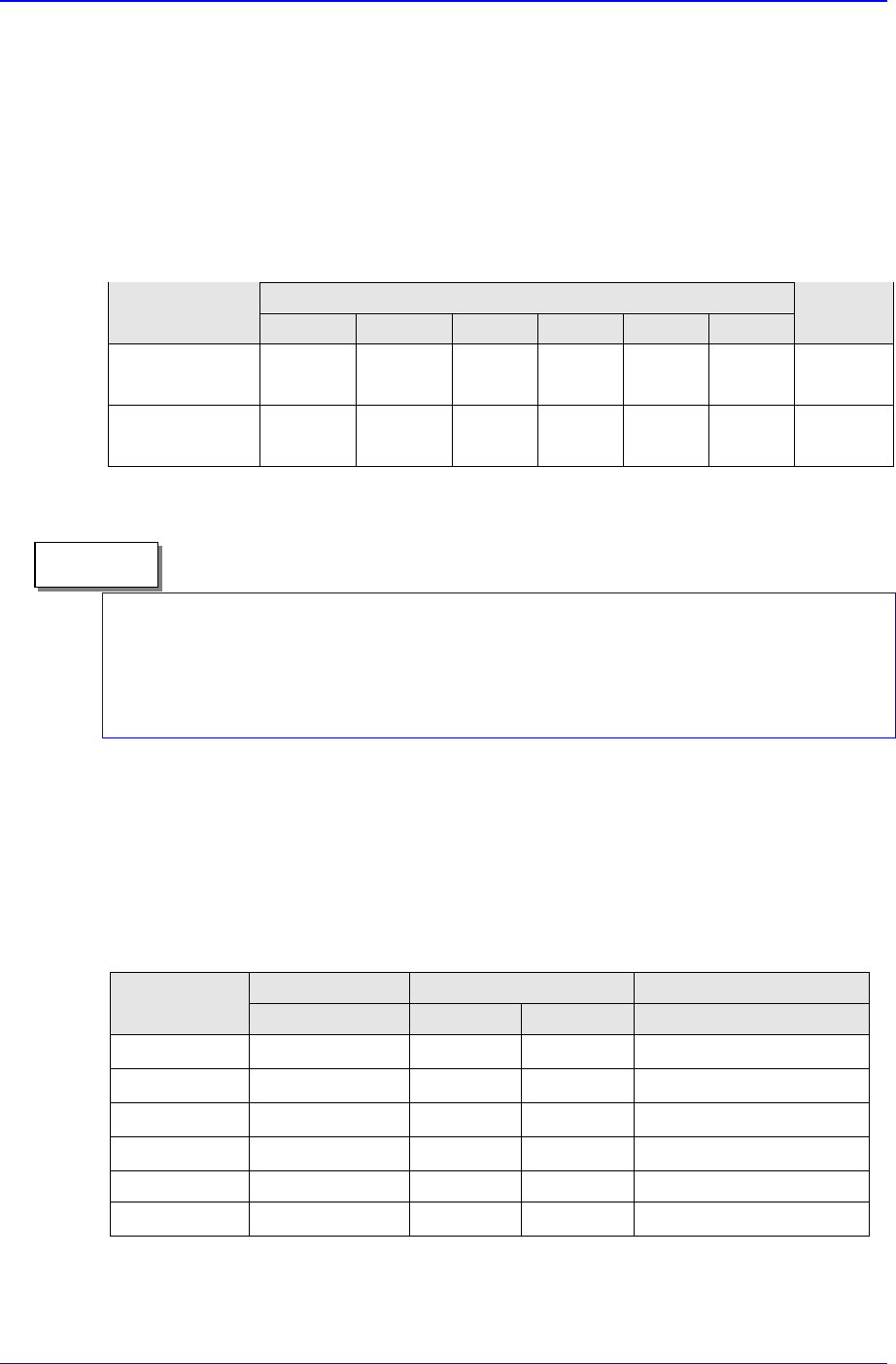
2.11.1. Configuration of the head and vision recognition system
The configuration of the head and vision recognition system of the CP-45FV model
relevant to the components to be placed is as shown in Table 2-3.
Table 2-3. Configuration of the Head and Vision Recognition System
Head Structure
Classification
Head 1 Head 2 Head 3 Head 4 Head 5 Head 6
Vision
System
CP-45FV
25mm
Vision
25mm
Vision
25mm
Vision
25mmV
ision
25mmV
ision
25mmV
ision
- 35mm
Vision
CP-45F
25mm
Vision
25mm
Vision
25mm
Vision
25mmV
ision
25mmV
ision
25mmV
ision
The 20 mm vision recognition systems for the placement of components requiring extra
precision (for example, 0.3mm fine pitch QFP, etc.) are provided as an option, and can be
used by simply replacing the upward vision unit. (Please refer to “1.2.2 Applicable
component sizes (page 1-3)”)
2.11.2. Component alignment mode and component specifications
2.11.2.1. Vision recognition system
2.11.2.1.1. For the case of 35mm vision
Table 2-4. Component Position Recognition for the Case of 35mm Vision
Size (mm) Lead Pitch(mm) One-way Lead Number
IC TYPE
Maximum Minimum Maximum Minimum
QFP
□ 32
0.4 3.0 4 Pin
SOP
□ 32
0.4 3.0 4 Pin
PLCC
□ 32
1.0 3.0 4 Pin
SOJ
□ 32
1.0 3.0 4 Pin
Connector 32(length) 0.5 3.0 4 Pin
BGA
□ 32
1.0 1.5 4 Ball
Memo