operation-cp45.pdf - 第76页
Samsung Component Placer CP-45F(V)/FS Operations Manual 2-24 2.11.2.1.2. For the case of 45mm vision T able 2-5. Component Position Rec ognition for the Case of 45mm V ision Size (mm) Lead Pitch(mm) One-w ay Lead Number …
Basic Configuration and Name of Each Part
2-23
2.11. Component Alignment Method (Centering Method) and Component
Relationships
2.11.1. Configuration of the head and vision recognition system
The configuration of the head and vision recognition system of the CP-45FV model
relevant to the components to be placed is as shown in Table 2-3.
Table 2-3. Configuration of the Head and Vision Recognition System
Head Structure
Classification
Head 1 Head 2 Head 3 Head 4 Head 5 Head 6
Vision
System
CP-45FV
25mm
Vision
25mm
Vision
25mm
Vision
25mmV
ision
25mmV
ision
25mmV
ision
- 35mm
Vision
CP-45F
25mm
Vision
25mm
Vision
25mm
Vision
25mmV
ision
25mmV
ision
25mmV
ision
The 20 mm vision recognition systems for the placement of components requiring extra
precision (for example, 0.3mm fine pitch QFP, etc.) are provided as an option, and can be
used by simply replacing the upward vision unit. (Please refer to “1.2.2 Applicable
component sizes (page 1-3)”)
2.11.2. Component alignment mode and component specifications
2.11.2.1. Vision recognition system
2.11.2.1.1. For the case of 35mm vision
Table 2-4. Component Position Recognition for the Case of 35mm Vision
Size (mm) Lead Pitch(mm) One-way Lead Number
IC TYPE
Maximum Minimum Maximum Minimum
QFP
□ 32
0.4 3.0 4 Pin
SOP
□ 32
0.4 3.0 4 Pin
PLCC
□ 32
1.0 3.0 4 Pin
SOJ
□ 32
1.0 3.0 4 Pin
Connector 32(length) 0.5 3.0 4 Pin
BGA
□ 32
1.0 1.5 4 Ball
Memo
Samsung Component Placer CP-45F(V)/FS Operations Manual
2-24
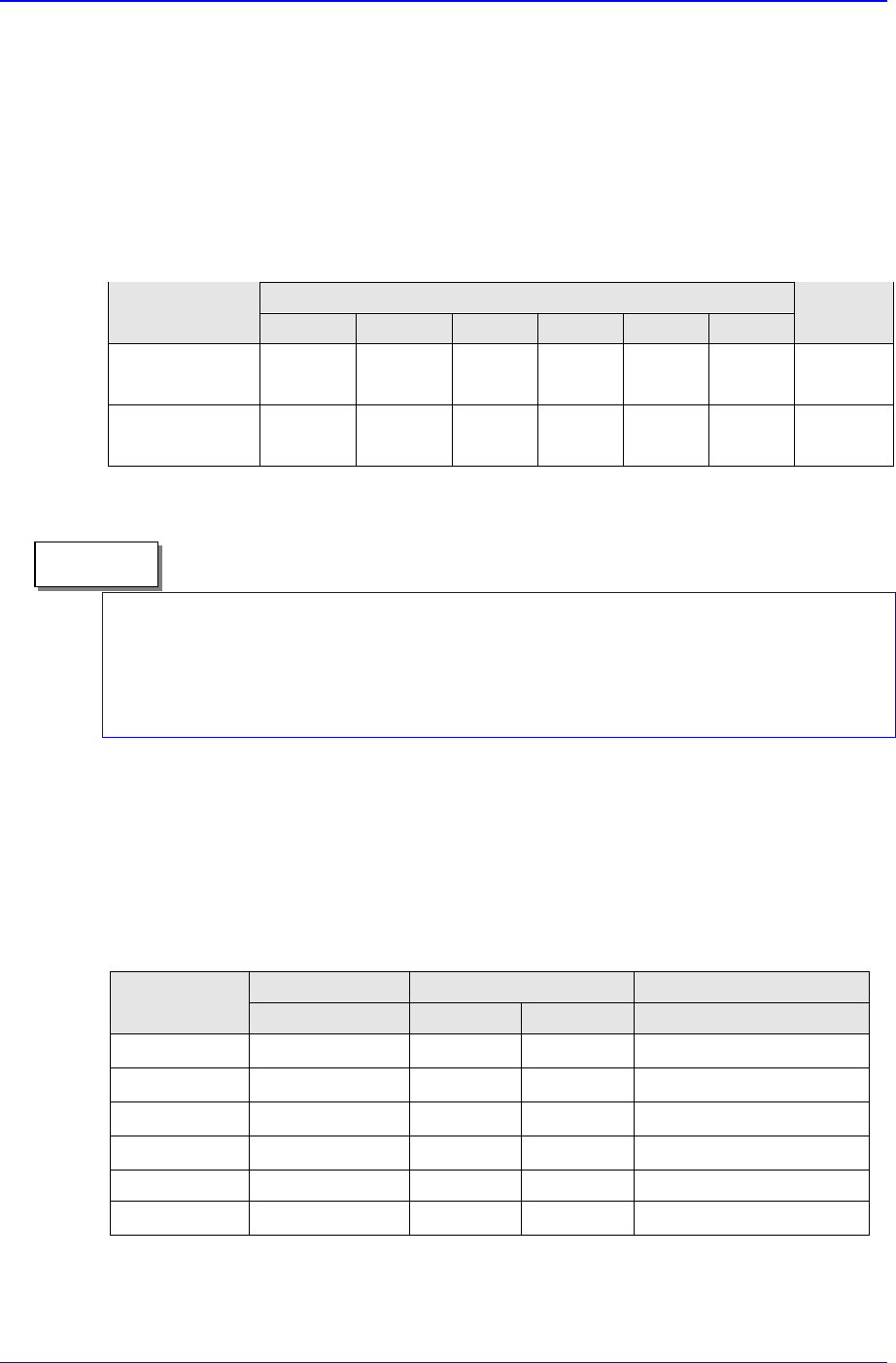
2.11.2.1.2. For the case of 45mm vision
Table 2-5. Component Position Recognition for the Case of 45mm Vision
Size (mm) Lead Pitch(mm) One-way Lead Number
IC TYPE
Maximum Minimum Maximum Minimum
QFP
□ 42
0.5 4.0 4 Pin
SOP
□ 42
0.5 4.0 4 Pin
PLCC □ 42 1.0 4.0 4 Pin
SOJ
□ 42
1.0 4.0 4 Pin
Connector 42(length) 0.5 4.0 4 Pin
BGA
□ 42
1.0 1.5 4 Ball
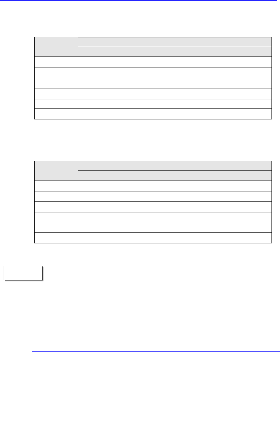
2.11.2.1.3. For the case of 20mm vision (optional)
Table 2-6. Component Position Recognition for the Case of 20mm Vision
Size (mm) Lead Pitch(mm) One-way Lead Number
IC TYPE
Maximum Minimum Maximum Minimum
QFP
□ 18
0.3 2.0 4 Pin
SOP
□ 18
0.3 2.0 4 Pin
PLCC
□ 18
1.0 2.0 4 Pin
SOJ
□ 18
1.0 2.0 4 Pin
Connector 18(length) 0.5 2.0 4 Pin
BGA
□ 18
1.0 1.5 4 Ball
It is possible in the CP-45FV model to place 0.3mm pitch and 32.0 mm QFP.
However, in this case, a separate upward vision unit (fixed type) should be ed.
(optional)
In the CP-45FV model, general components not mentioned in Table 2-6 can be
placed. If you intend to place non-standard components not mentioned in Table 2-6,
please contact our Business Department or C/S Center.
Memo
Basic Configuration and Name of Each Part
2-25
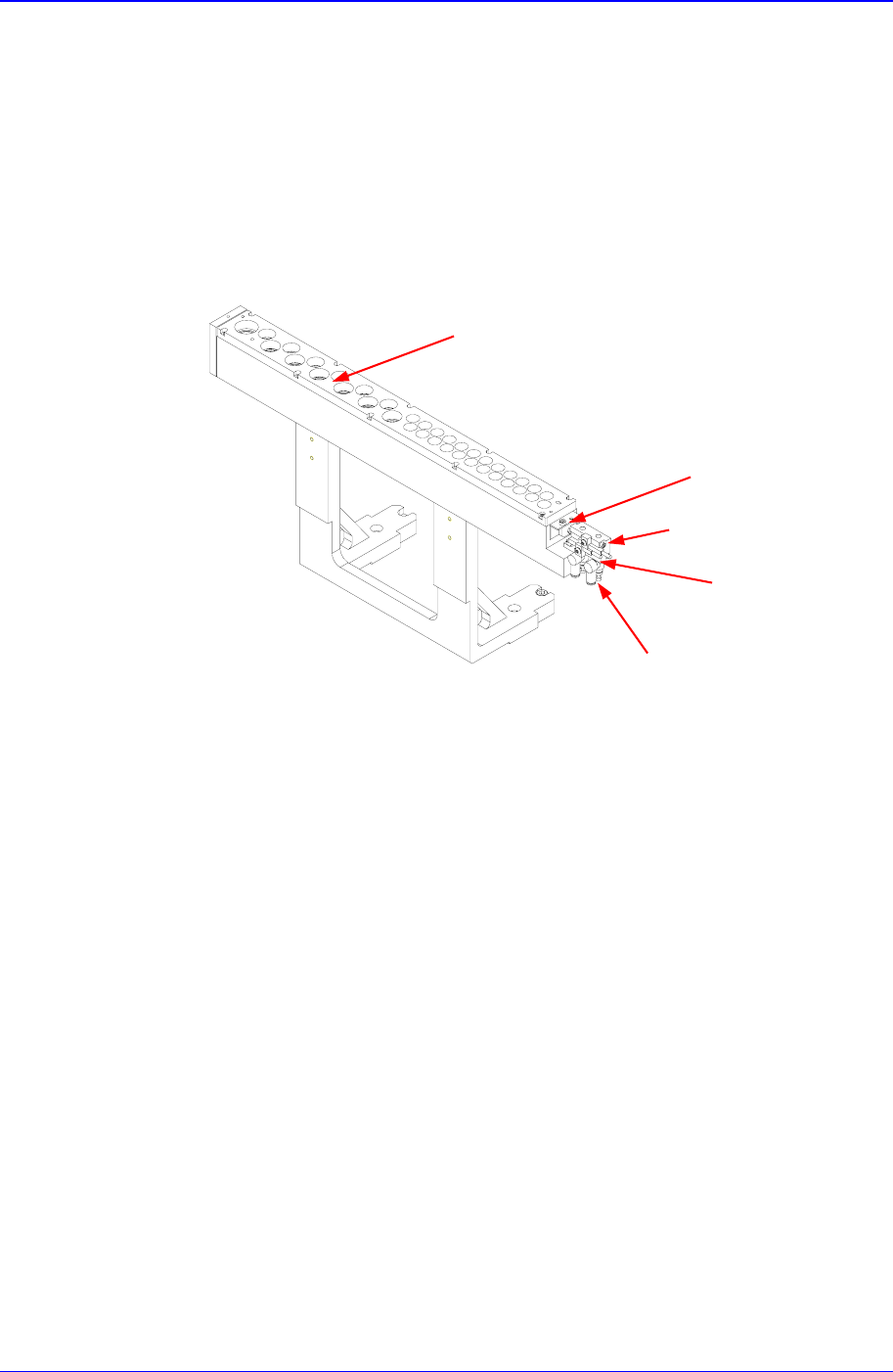
2.12. ANC (Auto Nozzle Changer)
ANC is fixed to the equipment, and in another type, the user can freely attach to or detach
from the feeder base.
Twenty nozzle pockets for various types of components are employed. ANC and gripper
ANC are composed of the alignment part for aligning the nozzle and the shutter part for
holding and guiding the nozzle.
Figure 2-18. 37-Hole ANC (fixed to the equipment)
ANC is an automatic nozzle-switching device that detaches or attaches as the nozzles are
switched to accommodate the component type during the process. The shutter is opened
or closed by a cylinder. Whether the shutter is currently open or closed can be confirmed
by a limit sensor attached to the cylinder.
The connectors for the sensor and the air pressure line are connected to the connector
panel attached to the feeder station cover. Air pressure is generally set 4.5 - 5.5 kgf/㎠.
The air flows in through the main inlet located at the bottom of the rear side of the
equipment, and is used for operating the head, ANC, etc.
Open/close speed of the ANC shutter is controlled by a speed control valve attached to
the cylinder. Up to 20 nozzles can be attached to ANC, and the time duration for
switching of the nozzle is about 0.5 seconds.
As the nozzle of ANC can be set easily at any position, it is possible to either increase
pickups rate or to shorten the placement time by reducing the frequency of the nozzle
switching.
Because ANC is located at the inside of the feeder base, the number of able feeders is not
Shutter
Open/Close Cylinder
Limit Sensor
Speed Control Valve
Align