operation-cp45.pdf - 第53页
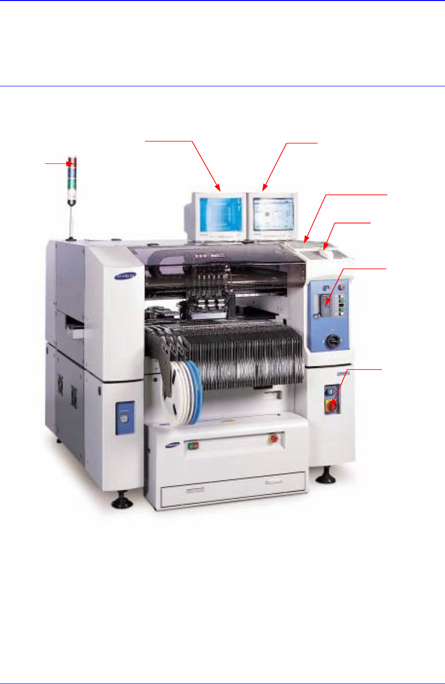
Basic Configuration and Name of Each Part 2-1 Chapter 2. Basic Configuration and Name of Each Part 2.1. Exterior (Name of Each Part) Figur e 2-1. Equipment Exterior (Fr ont V iew) Programming Monitor K eyboa r d Mouse T …
Samsung Component Placer CP-45F(V)/FS Operations Manual
1-14
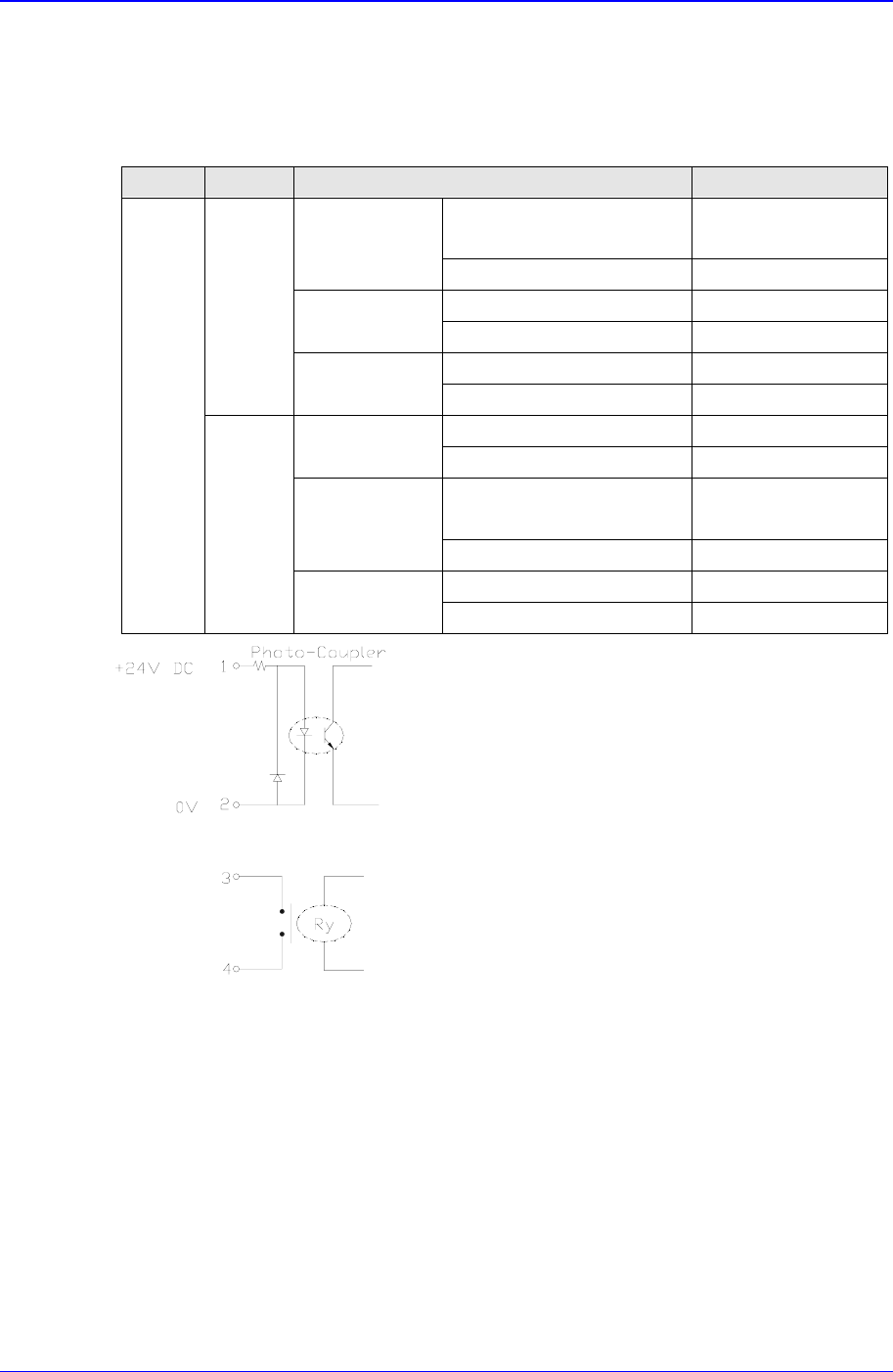
1.5.5. Connections with peripheral units
1.5.5.1. Signals and interface
Table 1-6. Signals and Interface
Signal Item Specifications Remark
PIN No.1: (+)Input Signal Less than
24 V/10mA
Busy Input(In)
PIN No.2: (-) Ground
PIN No.3: Contact output
Board Available
Output(Out)
PIN No.4: Contact output
AMP 206043-1 Machine Side
From
Next
M/C
Connector
AMP 206044-1 External Connection
PIN No.1: Contact output
Busy
Output(Out)
PIN No.2: Contact output
PIN No.3: (+) Input Signal Less than
24 V/10mA
Board Available
Input(In)
PIN No.4: (-) Ground
AMP 206043-1 Machine Side
In-Line
Signal
From
Pervious
M/C
Connector
AMP 206044-1 External Connection
Figure 1-4. Interface
1.5.5.2. Connectors
Socket for tray feeder: 25 pin D-sub
Socket for RS232C: 25 pin D-sub
Socket for printer: 25 pin D-sub
Teaching Box Connector: HR10A-7R-6S
Connector for ANC: 6 Pin Circular Type
Connector for Stick feeder: 6 Pin Circular Type
Basic Configuration and Name of Each Part
2-1
Chapter 2. Basic Configuration and Name
of Each Part
2.1. Exterior (Name of Each Part)
Figure 2-1. Equipment Exterior (Front View)
Programming Monitor
K
eyboa
r
d
Mouse
Teaching Box
Isolation Switch
Teaching Monitor
Signal Towe
r
Samsung Component Placer CP-45F(V)/FS Operations Manual
2-2
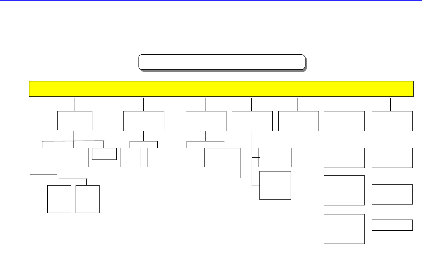
2.2. System Configuration
2.2.1. Mechanical part configuration
CP-45FV Mechanical Part Configuration
BODY FRAME
Mirror
Driving
Part
Side ILL.
Driving
Part
UPWARD
CAMERA
Electric Part &
COVER
35mm
CAMERA
CONTROL
BOX
45mm
CAMERA
(OPTION)
CONTROL
BOX
20mm
CAMERA
(OPTION)
COVER
FEEDER
BASE
HEAD
(6NOZZLE)
X-Y
GANTRY
X
AXIS
Y
AXIS
FLYING
CAMERA
UNIT
FIDUCIAL
CAMERA
UNIT
NOZZLE
Fixed ANC
(36POCKET)
Correct Tool
(1POCKET)
ANC
UNIT
3Stage
CONVEYOR
Driving-Motor
Adjust Width
(OPTION)
CONVEYOR
UNIT
Figure 2-2. Mechanical Part Configuration Diagram