operation-cp45.pdf - 第184页
Samsung Component Placer CP-45F(V)/FS Operations Manual 11-30 Figur e 1 1-22. Flowchart of “ Delay T ime during Placement ” <Speed> group Set the speed for each axis during pickups, placement, and dumping operati…

PCB Edit Command
11-29
Belt Multi Stick: Supply by Belt Multi Stick Feeder.
Single Tray: Supply by Single Tray Feeder.
FW-20F: Supply by 20-stage Tray Feeder.
FW-20S: Supply by 20-stage Tray Feeder.
FW-12M: Supply by 12-stage Tray Feeder.
<Nozzle1> combo box: Displays the nozzle that pick up the component. The
types of nozzles are as follows
NP20:
NP40:
TNSQ:
TN14:
TN22:
TNDSQ:
TN40:
TN75:
TN110:
<Nozzle2> combo box: Displays the auxiliary nozzle that adsorbs the
component. When the main nozzle can not be used, the auxiliary nozzle is
used. The types of auxiliary nozzles are the same as the main nozzle.
<Etc> group
<Sync Pick X> edit box: Set the allowance in X direction as a percentage of
Part Size X at the time of synchronized pick up.
<Sync Pick Y> Set the allowance in Y direction as a percentage of Part Size
Y at the time of synchronized pick up.
<Retry> combo box: Set the number of retries when the component pickups
was not successful. Available numbers are 1 - 3.
<Vacuum Check> check box: Check it to carry out vacuum check during
component pickups.
<Delay> group
Set various delay time for pickups, placement, and dump operations.
<Pick Up> edit box: During component pickups, the delay time after the
head has come down until the head starts ascending.
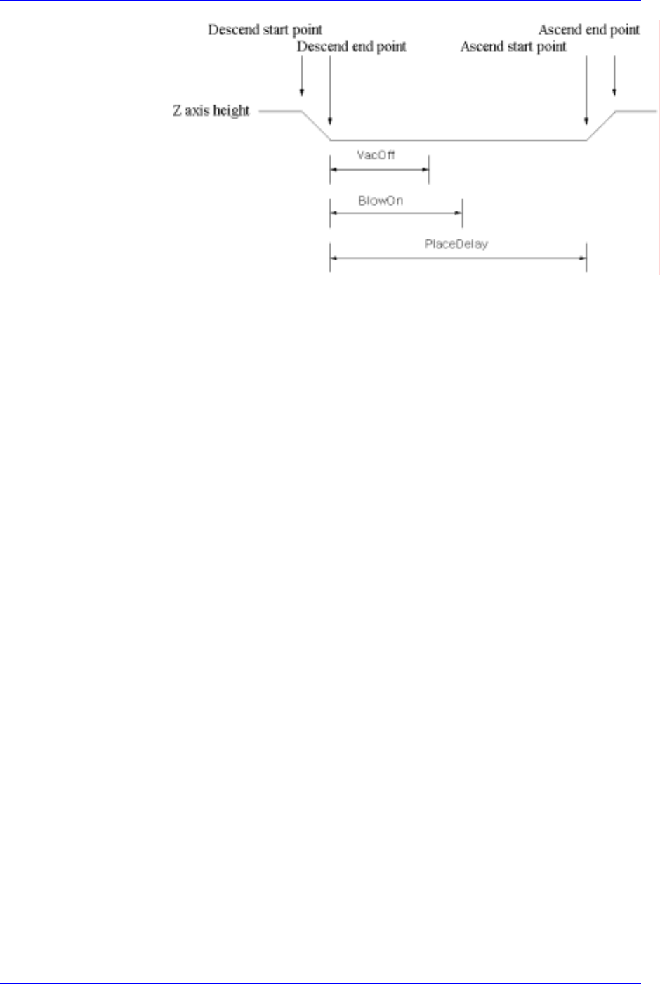
<Place> edit box: During component placement, the delay time after the
head has come down until the head starts ascending.
<Vac Off> edit box: During component placement, the delay time after the
head has come down until vacuum is off.
<Dump> edit box: During component dumping, the delay time after the head
has come down until the head starts ascending.
<Dump Vac Off> edit box: During component dumping, the delay time after
the head has come down until vacuum off.
Samsung Component Placer CP-45F(V)/FS Operations Manual
11-30
Figure 11-22. Flowchart of “Delay Time during Placement”
<Speed> group
Set the speed for each axis during pickups, placement, and dumping
operations. The speeds are as follows, and the profile of each moving speed
is set in the system.
1- Fastest: The fastest speed.
2- Fast: Fast speed.
3- Middle: Middle speed.
4- Slow: Slow speed.
5- Slowest: The slowest speed.
<XY> combo box: Select the speed for XY axis
<R> combo box: Select the speed of R axis.
<Z Pick Down> combo box: Select the speed for Z axis when the head is
lowered for component pickups.
<Z Pick Up> combo box: Select the speed for Z axis when the head is
ascending after component pickups.
<Z Place Down> combo box: Select the speed for Z axis, when the head is
lowered for placement.
<Z Place Up> combo box: Select the speed for Z axis, when the head is
ascending after placement.
<Register> button
Adds the set component data to the PCB part list.
<Close> button
Closes the dialog box.
<Edit…> button
Edits the selected component data.
<Duplicate…> button
Copies the selected component data. At this time, new component name must be
set.
<Copy> button
Copies the part data selected from the Part list box.
PCB Edit Command
11-31
<Paste> button
Pastes the copied part data to the Part list box.
<Delete> button
Deletes the part selected in the Part list box.
<2. Library> group
Display the component list of the Local Part DB managed by the equipment.
<Align Type> combo box
Select the align type of the component to be displayed. Available align types are
as follows.
None: No alignment.
Chuck: Alignment by the Chuck.
QA: Alignment by the Quad Aligner.
CA: Alignment by the Cyber Optics.
Vision: Alignment by the Vision Camera.
<Part Group> combo box
Select the group of component to be displayed. Available component groups are
as follows.
( CHIP-Circle:, CHIP-Rect:, Melf:, TR:, Trimmer:, Hemt:, SOP:, SOJ:, SOP2:,
SOJ2:, QFP:, PLCC:, Connector-1:, Connector-2:, User IC:, BGA: )
<Part List> list box
Displays the component data list of the data selected in <Align Type> and
<Part Group>.
<Update Part> button
After adding a New Part, use it to add the New part to the Local DB.
<Change Group> button
Changes the group of the selected part from current part group to another group.
<Library Delete> button
Deletes the component data selected in <Part List> from the Local Part DB.
<Copy to PCB Part>
button
Copies the component data selected in <Part List> of <2. Library> group to <1. PCB
Part List> group.
<Copy to Local Part DB>
button
Copies the component data selected in the <1. PCB Part List> group to the Local Part
DB.
<Copy All to Local Part DB>
button
Copies all component data in the <PCB Part List> group to the Local Part DB.
<Cancel> button
Cancels all edited data.
Caution - If you move to another screen while editing the “Part” dialog box, the edited
data is saved automatically.