operation-cp45.pdf - 第248页
Samsung Component Placer CP-45F(V)/FS Operations Manual 11-94 When you want to start a new cycle, check this check box. <CY> column When <Cycle> is clicked on, the corresponding cycle number is displayed. …
PCB Edit Command
11-93
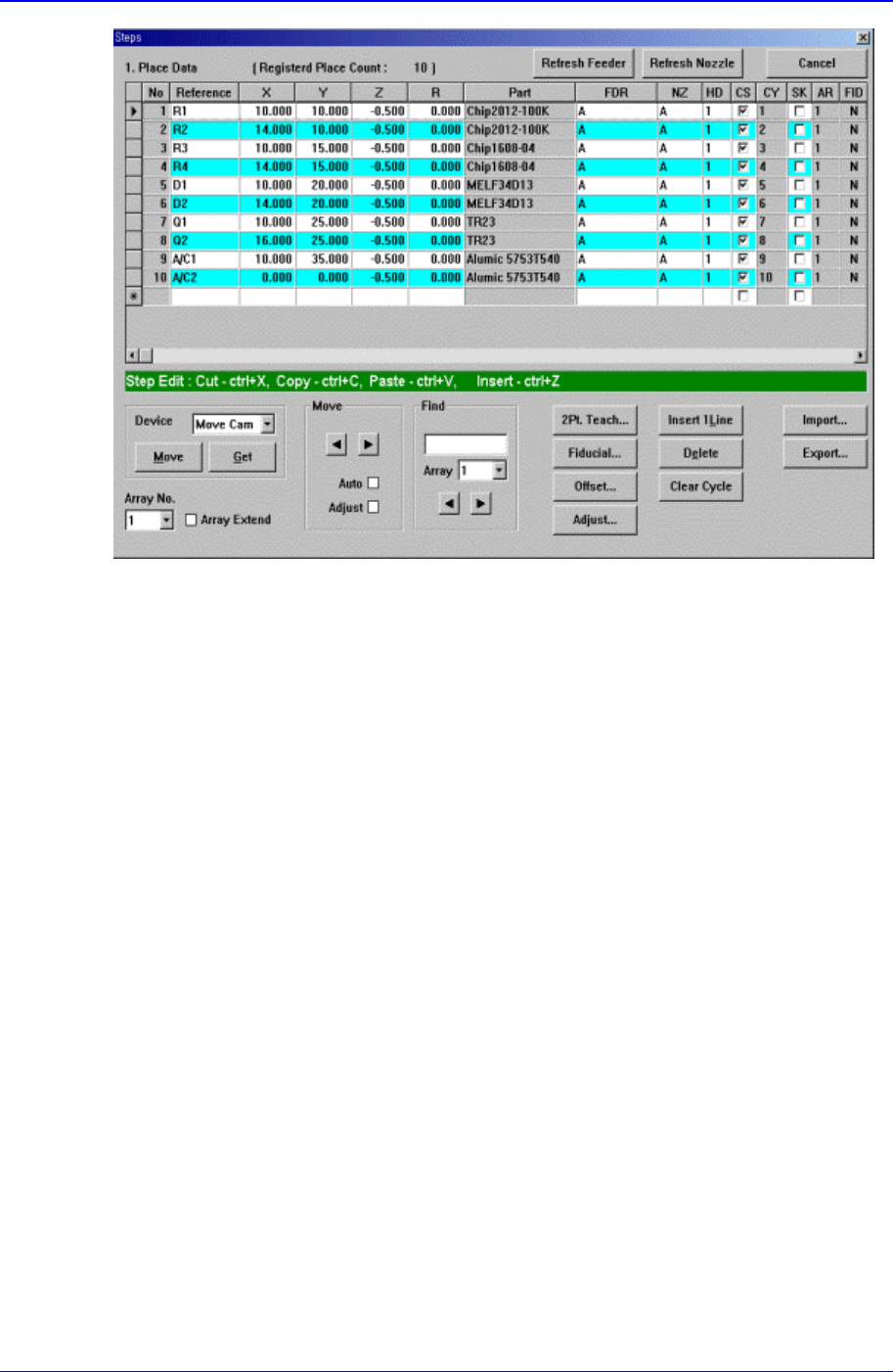
Figure 11-54 “Steps” Dialog box (Initial screen without placement point)
<1. Place Data> group
Set the edit data related to placement.
<Reference> column
Set the reference name of the placement point. In general, enter the value of R1,
R2, C1, and C2 on the PCB(up to 8 characters).
<X> column
Set the X position of the placement point.
<Y> column
Set the Y position of the placement point.
<Z> column
Set the Z position of the placement point.
<R> column
Set the R position(rotation angle of the placement component) of the placement
position.
<Part> column
Select the component to place.
<FDR> column
Select the feeder to supply the component.
<NZ> column
Select the nozzle to pick up the component.
<HD> column
Select the head to pick up the component.
<CS> column

Samsung Component Placer CP-45F(V)/FS Operations Manual
11-94
When you want to start a new cycle, check this check box.
<CY> column
When <Cycle> is clicked on, the corresponding cycle number is displayed.
<SK> column
Check the check box when you want to skip the placement point.
<AR> column
Select the array PCB number to which the placement point belongs.
<FID> column
If the fiducial mark data of the placement point has been set in <Fiducial…>, “Y”
is displayed, if not “N” is displayed.
<Device> combo box
To move or to read in the current position of the XY, Z, and R axes, select the
corresponding device. Available devices are as follows.
Move Cam: Selects Teaching Camera.
Head1: Selects Head1.
Head2: Selects Head2.
Head3: Selects Head3.
Head4: Selects Head 4.
Head5: Selects Head5.
Head6: Selects Head6.
<Move> button
Moves the XY, Z, and R axes to the device selected in <Device>. At this time, the
cell in the grid corresponding to the desired position must be clicked on with a mouse.
<Get> button
Reads in the current position of XY, Z, and R axes of the device selected in <Device>.
At this time, the cell in the grid corresponding to the desired position must be clicked
on first with a mouse.
<Array No.> combo box
Displayed only in the case of Array PCB.
Select the array PCB number to move.
<Array Extend> check box
Displayed only in the case of Array PCB.
Expand the placement point to one PCB by using the offset value of array PCB.
For example, if the number of current placement points is 10 and the number of array
PCB is 4, then the total number of placement points is expanded to 40.
If it is already expanded, returns to the original status. At this time, all placement data
disappear except for no. 1 array PCB.
<Move> group
Moves the XY axis to the placement point on the line before or after the current line
in the grid.
<Move Prev>
button
Moves the XY axis to the placement point on the previous line of the current line
PCB Edit Command
11-95
in the grid
<Move Next>
button
Moves the XY axis to the placement point on the next line of the current line in
the grid.
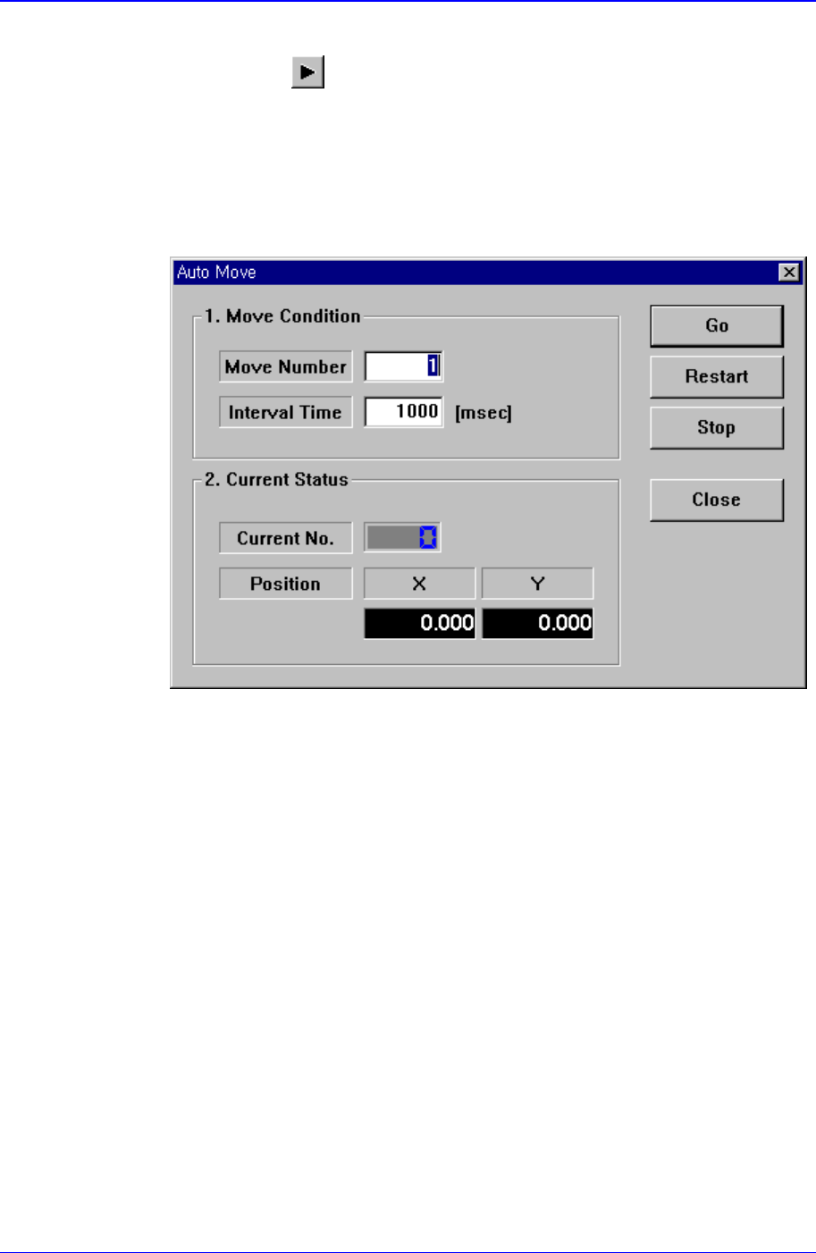
<Auto> check box
To move continuously, check this check box. When this check box has been
clicked on and <Move Prev> or <Move Next> is clicked on, the following dialog
box is displayed.
<1. Move Condition> group
Set the number of placement points to move and the time interval between
movement.
Move Number: Set the number of placement points to move continuously.
Interval Time: Set the time interval between placement point movements.
<2. Current Status> group
Displays the number and position of the current placement point.
Current No.: Displays the current placement point number.
Position X: Displays the X position of the current placement point.
Position Y: Displays the Y position of the current placement point.
<Adjust> check box
Displayed only when the fiducial mark has been set.
To move after adjusting by using the fiducial mark of the PCB, check this check
box.
<Find> group
Edit box