operation-cp45.pdf - 第71页
Basic Configuration and Name of Each Part 2-19 2.10.1.3. Illumination The flying vision system provides 3 types of lights for each head. Figur e 2-13 Illumination 2.10.1.3.1. Side Light The side light is a light illumina…
Samsung Component Placer CP-45F(V)/FS Operations Manual
2-18
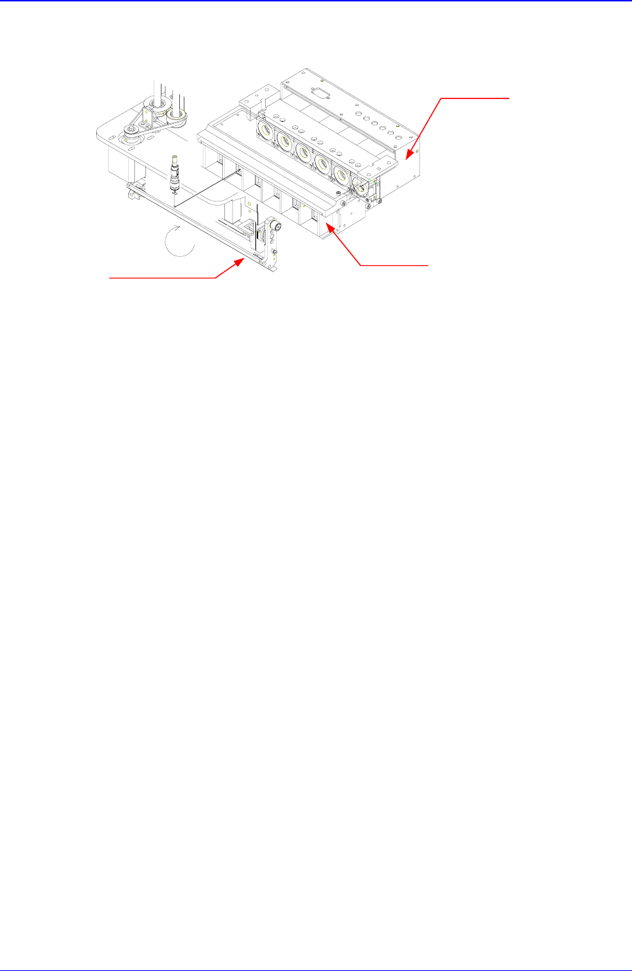
Figure 2-12. Light path control
During component pickups, the mirror attached on the head rotates and moves to the front
of the head. When the component is on the move to the placement position after it has
been picked up, the mirror rotates and moves to the bottom of the head, and the image of
the component is formed through the mirror on the CCD camera attached on the head.
The image is vision treated and the position and angle of the component is recognized. By
using the recognized position and angle of the component, the coordinates of placement
position are adjusted. When the component is placed on the adjusted position, the mirror
rotates and moves to the front of the head again.
Multi-Step digital
lighting system
6 – CCD Camera
Mirror
Basic Configuration and Name of Each Part
2-19
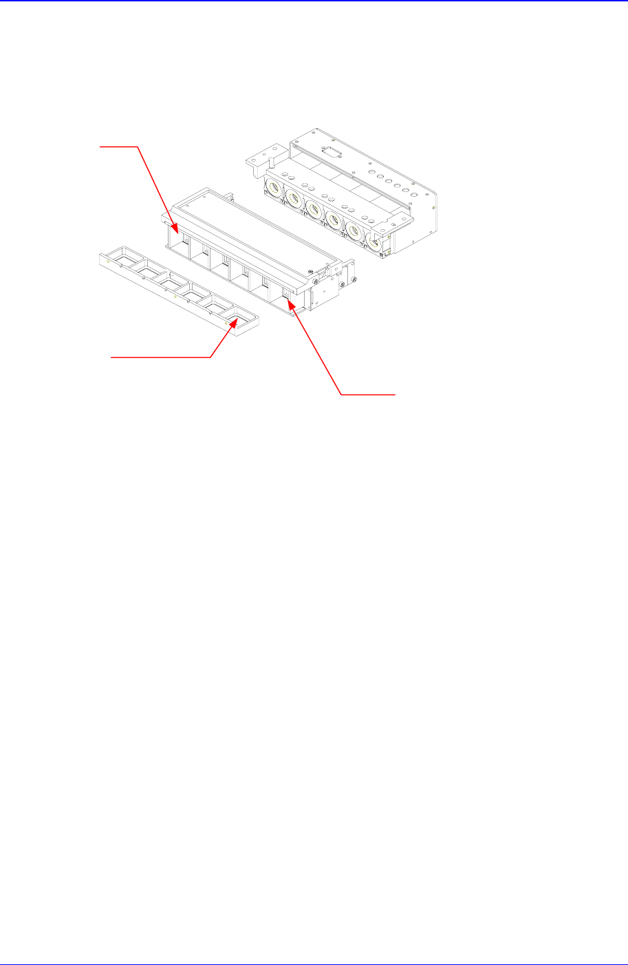
2.10.1.3. Illumination
The flying vision system provides 3 types of lights for each head.
Figure 2-13 Illumination
2.10.1.3.1. Side Light
The side light is a light illuminating from the side of the component. This light is installed
on a lighting system that moves to the Z axis. When it is not in use, it stays up, and when
a component is recognized, the device comes down and illuminates the component. This
light is used to illuminate the ball during BGA component recognition, and it is also used
to emphasize the outline of Chip and IC components. It is possible to control steps
between 0 - 15.
2.10.1.3.2. Outer Light
The outer light is a light illuminating obliquely from the front of the component. This
light exists between the lens and the mirror of the CCD camera and it illuminates the
entire component. It is used for most components and it is possible to control steps
between 0-15.
2.10.1.3.3. Inner Light
The inner light is a light illuminating straightly from the front of the component. It exists
right in front of the CCD camera lens, it is used for components that cause a lot of
reflection. It is used for odd type components such as connector and it is possible to select
Side Light
Inner Light
Outter Light
Samsung Component Placer CP-45F(V)/FS Operations Manual
2-20
On or Off.
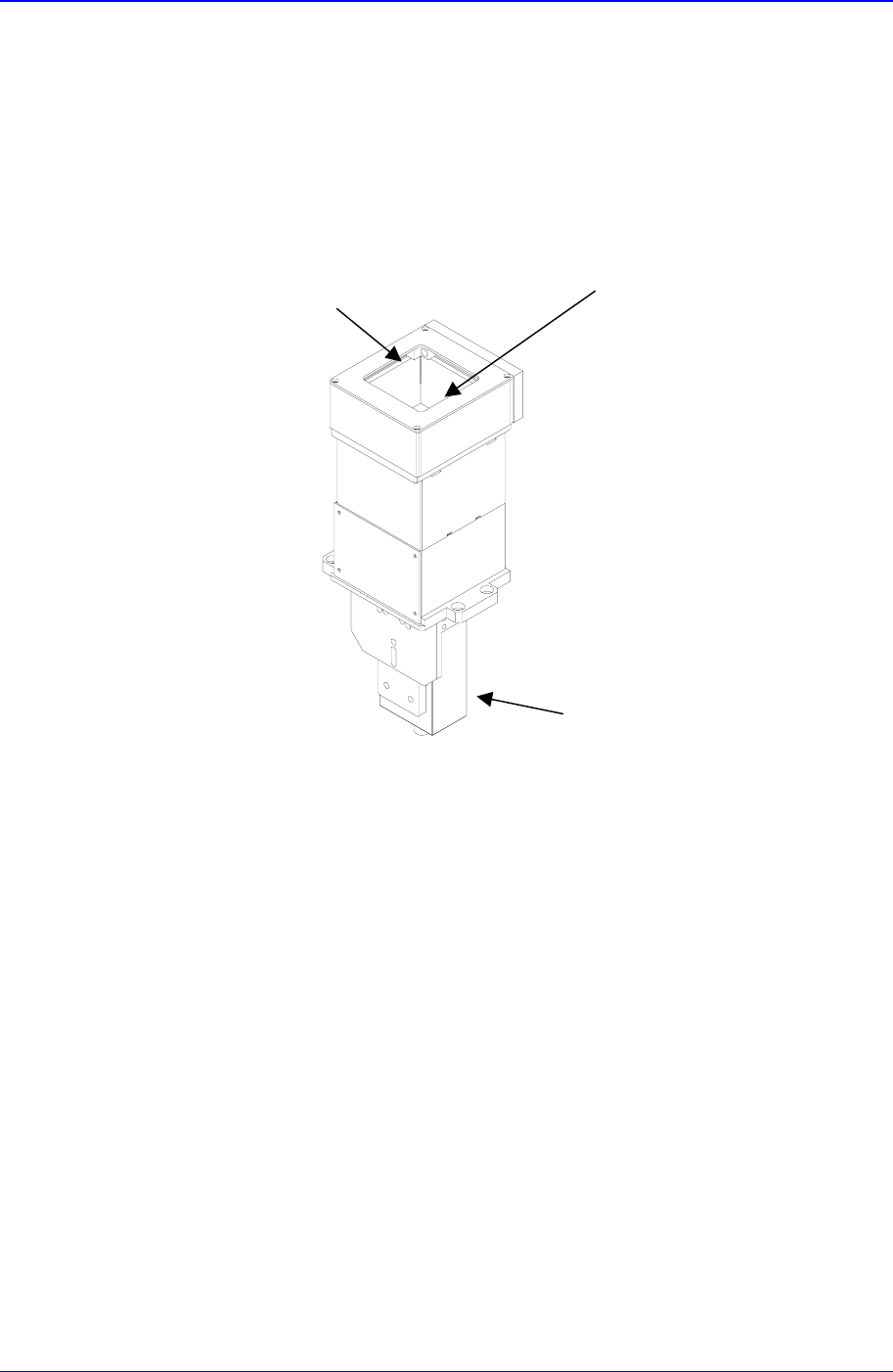
2.10.2. Upward vision unit(For CP-45FV)
The upward vision unit of the CP-45FV model can recognize the general and Odd-type
components, and also has a digital lighting controller. Thus, safe and accurate recognition
and placement is possible.
Figure 2-14. Upward Vision Unit
2.10.2.1. Light path control
The optimum lighting conditions are achieved by selecting the lighting in the desired
direction according to the component to be measured as shown in “Figure 2-15“.
Cover Glass
LED
Camera