operation-cp45.pdf - 第61页
Basic Configuration and Name of Each Part 2-9 W idth adjustment part Adjusts the width of rails according to the si ze of PCB. It is composed of LM guide, lead screw, chain, handle. P CB belt assembly Composed of an …
Samsung Component Placer CP-45F(V)/FS Operations Manual
2-8
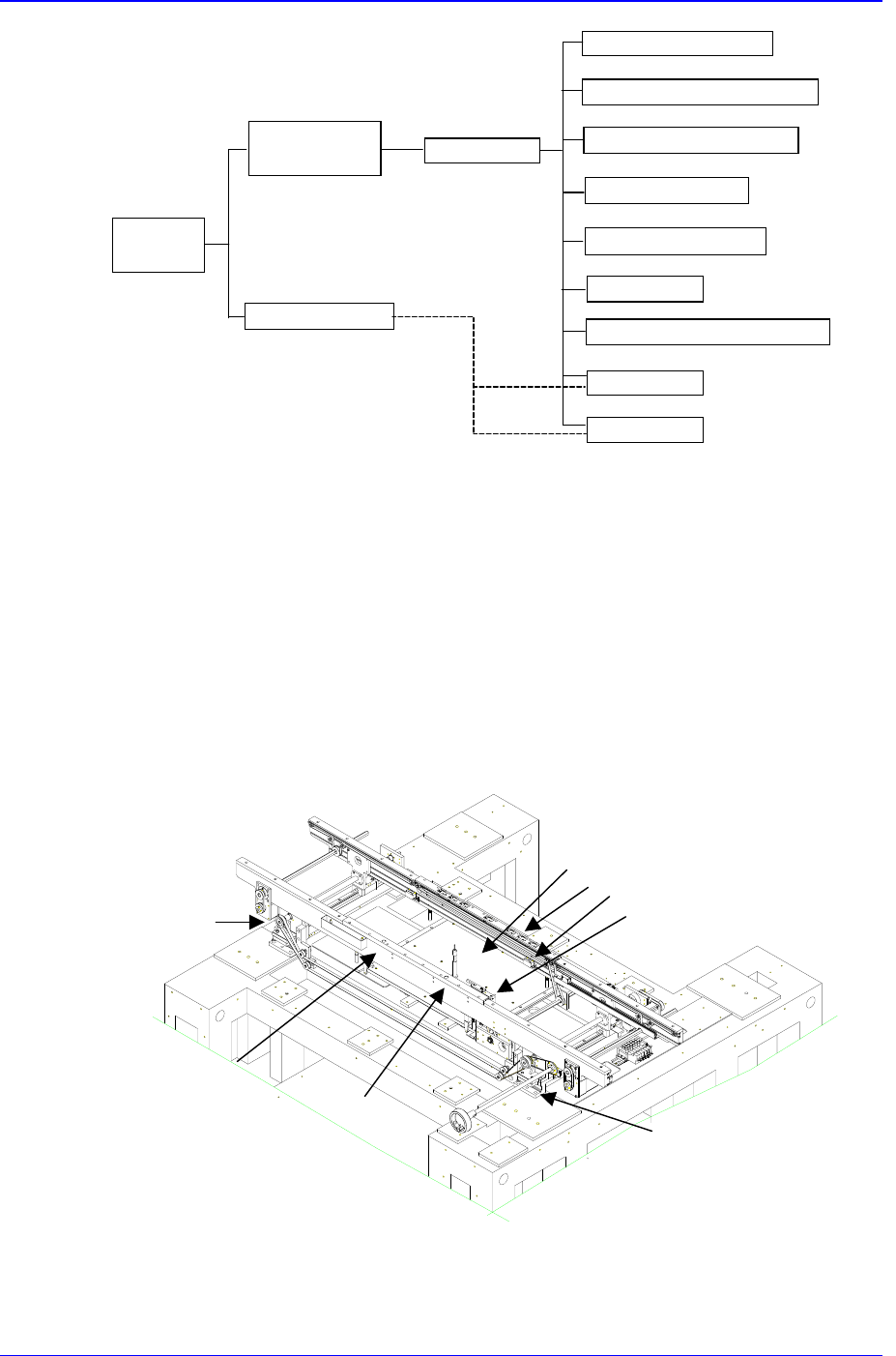
Conveyor
Part
Adjusting
Width Part
Back Up Table
Main Frame
PCB In Belt Ass`y
PCB Working Belt Ass`y
PCB Out Belt Ass`y
Working Stopper
PCB Detect Sensor
Edge Fixer
Auto Width Control Unit
PCB Clamp
Hole Fixer
Figure 2-7. PCB Conveyor System Configuration Diagram
2.6.2. Functions
Functions for each element are as follows.
Main Frame
It is attached on top of the width adjustment part, and serves as the basis of PCB flow.
Various parts are attached to it.
Figure 2-8. PCB Conveyor System Main Frame
Rear frame
Wait stopper
①
②
③
④
①Backup table
②Edge fixer
③PCB detection sensor
④Place stopper
Adjust conveyor
width (L)
Adjust conveyor
width (R)
Out stopper
Hole fixer (R)
Hole fixer (L)
Front frame

Basic Configuration and Name of Each Part
2-9
Width adjustment part
Adjusts the width of rails according to the size of PCB. It is composed of LM guide,
lead screw, chain, handle.
P
CB belt assembly
Composed of an AC (step) motor and a timing belt. For a 3-stage conveyor, PCB feed
belt is divided into three steps, and each is driven separately. For a 3-stage conveyor,
a PCB can be clamped by using a belt in the working area since in and out movement
of the PCB is possible without having to drive the belt in the working area.
Place stopper
Stops a PCB at a working position and hold the PCB in place until discharge if it is at
an out position.
PCB sensor
Checks the position of a PCB on the conveyor..
Edge fixer
This is one way of correcting the position of a PCB prior to the beginning of work
after the PCB has reached the working position. The correction is made in reference
to one side of the PCB by pushing into that edge.
PCB clamp
Holds a PCB that is in contact with the belt prior to the beginning of work after the
PCB has reached the working position. It is operated while interlocked with a back-
up table.
Hole fixer
This is another way of correcting the position of a PCB prior to the beginning of work
after the PCB has reached the working position. The correction is made in reference
to a hole in the PCB by inserting a pin into that hole. The hole fixer is operated while
interlocked with a back-up table.
Backup Table (BUT)
Caution
Adjusting the conveyor width without checking conveyor
obstruction or the existence of foreign substance could
damage the conveyor.
Be sure to check conveyor obstruction and the existence
of foreign substance before adjusting the conveyor width.

Samsung Component Placer CP-45F(V)/FS Operations Manual
2-10
This installs a back-up pin for maintaining the evenness of a PCB, and drives the
PCB clamp, hole fixer, etc., prior to the beginning of work after the PCB has reached
the working position.
Caution
Be sure to remove any foreign substance on the BUT and
obstruction before manipulating the BUT.
Otherwise, the conveyor might be damaged.