operation-cp45.pdf - 第236页
Samsung Component Placer CP-45F(V)/FS Operations Manual 11-82 <Stick> group Create and edit data according to the stic k unit type selected in the <T ype> combo box. If “ Multi Stick ” is selected for <T…
PCB Edit Command
11-81
<Device>. Before executing “Get”, the cell in the grid corresponding to the
desired position must be clicked on.
<OK> button
Sets the obtained center point as the new pickups point and closes the dialog box.
<Cancel> button
Ignores the obtained center point and closes the dialog box.
11.2.2. Stick Feeder
Install stick feeder and set data on the stick feeder.
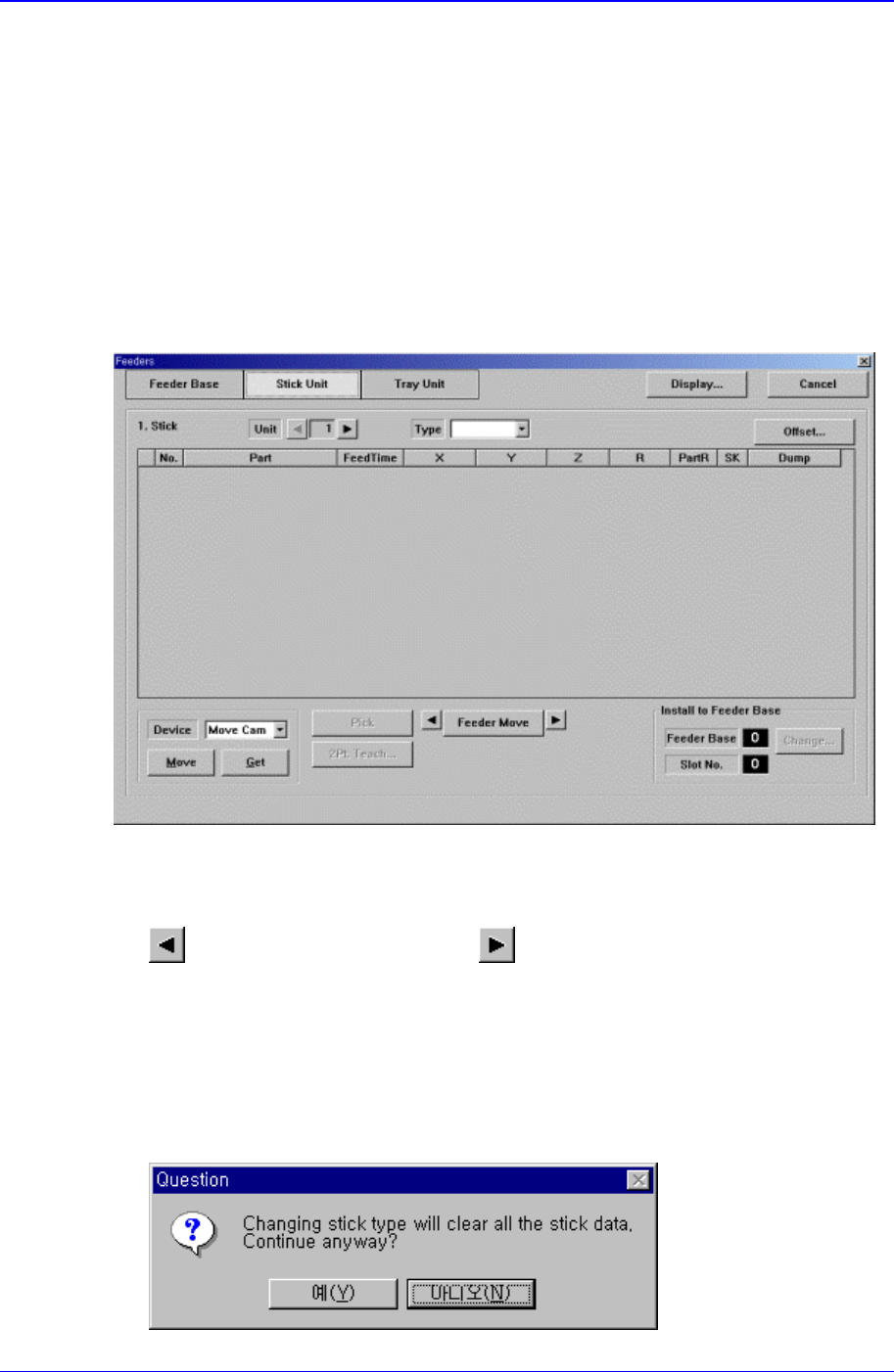
When “Stick Unit” is selected, the initial screen looks as follows.
Figure 11-51. “Stick Unit” dialog box
<Unit> group
Select the stick unit to edit.
button selects the previous unit, button selects the next unit.
<Type> combo box
Select the type of stick unit to install. Available types are as follows.
Stack Stick: Stick unit where the same type of components are installed vertically.
Multi Stick: One or many types of components are installed horizontally.
When the type is specified, the following message box is displayed. To install the
specified type stick unit, click on the <Yes> button.
Samsung Component Placer CP-45F(V)/FS Operations Manual
11-82
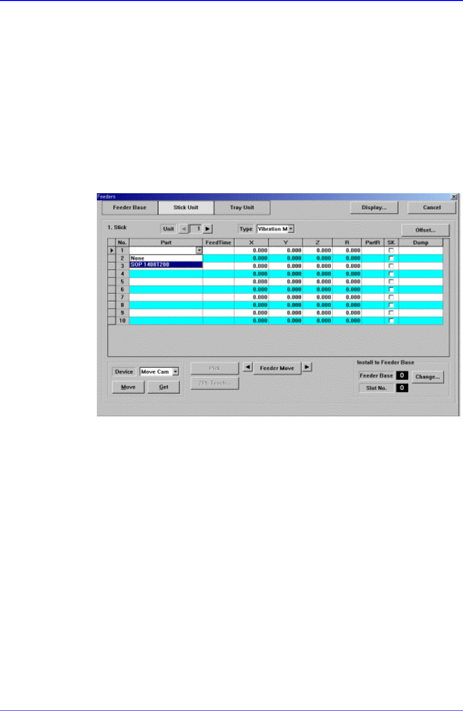
<Stick> group
Create and edit data according to the stick unit type selected in the <Type> combo
box. If “Multi Stick” is selected for <Type>, the following dialog box is displayed.
<No> column
A serial number of the stick unit slots. Basically, “Stack Stick” has 1, “Multi
Stick” has 10 slots.
<Part> column
Select the part to install in the corresponding slot. When the <Part> column is
clicked on, a combo box is displayed, and of the components registered in <1.2
Part>, a list of parts to be supplied to “Stick” are displayed. Select the component
to install in this list. Next is a screen showing component selection in the combo
box of <Part> column.
<FeedTime> column
When a stick feeder is installed in the corresponding slot, set the component
supply time of the stick feeder. Basically stick feeders are vibration type,
therefore certain time interval is necessary after a component is picked up until
the next component moves to the pickups position. The time is set here.
<X> column
When the stick feeder is installed in the corresponding slot, set the X position to
pick up the component supplied from the stick feeder.
<Y> column
When the stick feeder is installed in the corresponding slot, set the Y position to
pick up the component supplied from the stick feeder.
<Z> column
When the stick feeder is installed in the corresponding slot, set the Z position to
pick up the component supplied from the stick feeder.
<R> column
PCB Edit Command
11-83
When the stick feeder is installed in the corresponding slot, set the R
position(rotation angle of the head) to pick up the component supplied from the
stick feeder.
<PartR> column
When the stick feeder is installed in the corresponding slot, set the placement
angle of the component supplied from the stick feeder.
<SK> column
When the stick feeder is installed in the corresponding slot, select whether or not
to pick up the component supplied from the stick feeder.
To pick it up, leave the check box as it is, and not to pick it up, check the check
box.
<Dump> column
When the stick feeder is installed in the corresponding slot, select the dump box
for the component placed on the stick feeder. Available dump boxes are as
follows.
System Dump: The dump box set in the system, it is installed in the front of the
conveyor.
User Dump: The dump box set in the system by the user, the location should be
set in the system..
<Pick> button
Executes component pickups operation from the stick feeder installed on the current
line in the grid. At this time, the device must be selected first. When pickups is
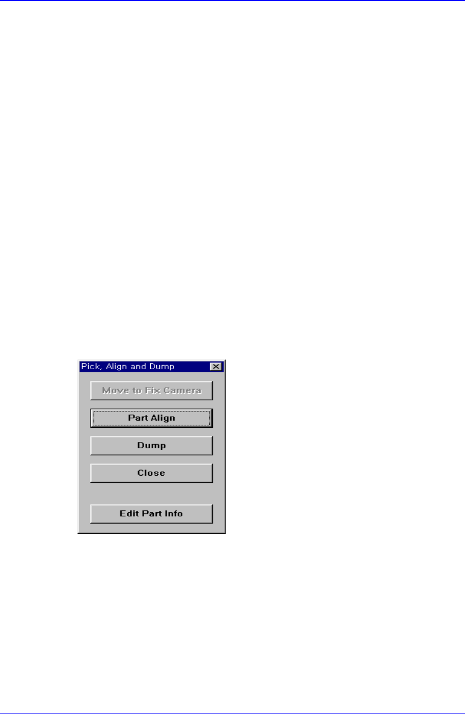
successful, the following dialog box is displayed.
<Move to Fix Camera> button
It is activated only when the corresponding component is aligned by the vision
camera and the align camera is fix camera. When this button is clicked on, moves
the head block to the position of the fix camera.
<Part Align> button
Executes alignment of the corresponding component.
<Dump> button
Dumps the corresponding component to the dump box.
<Close> button