operation-cp45.pdf - 第44页
Samsung Component Placer CP-45F(V)/FS Operations Manual 1-6 1.2.4.2. The pick & place cycle time for each model T able 1-5. The pick & place Cycle T ime for Each Model Classification CP-45FV Remarks Chip 0.197sec…
Features and Scope of Equipment
1-5
1.2.4.1. General features
Speed
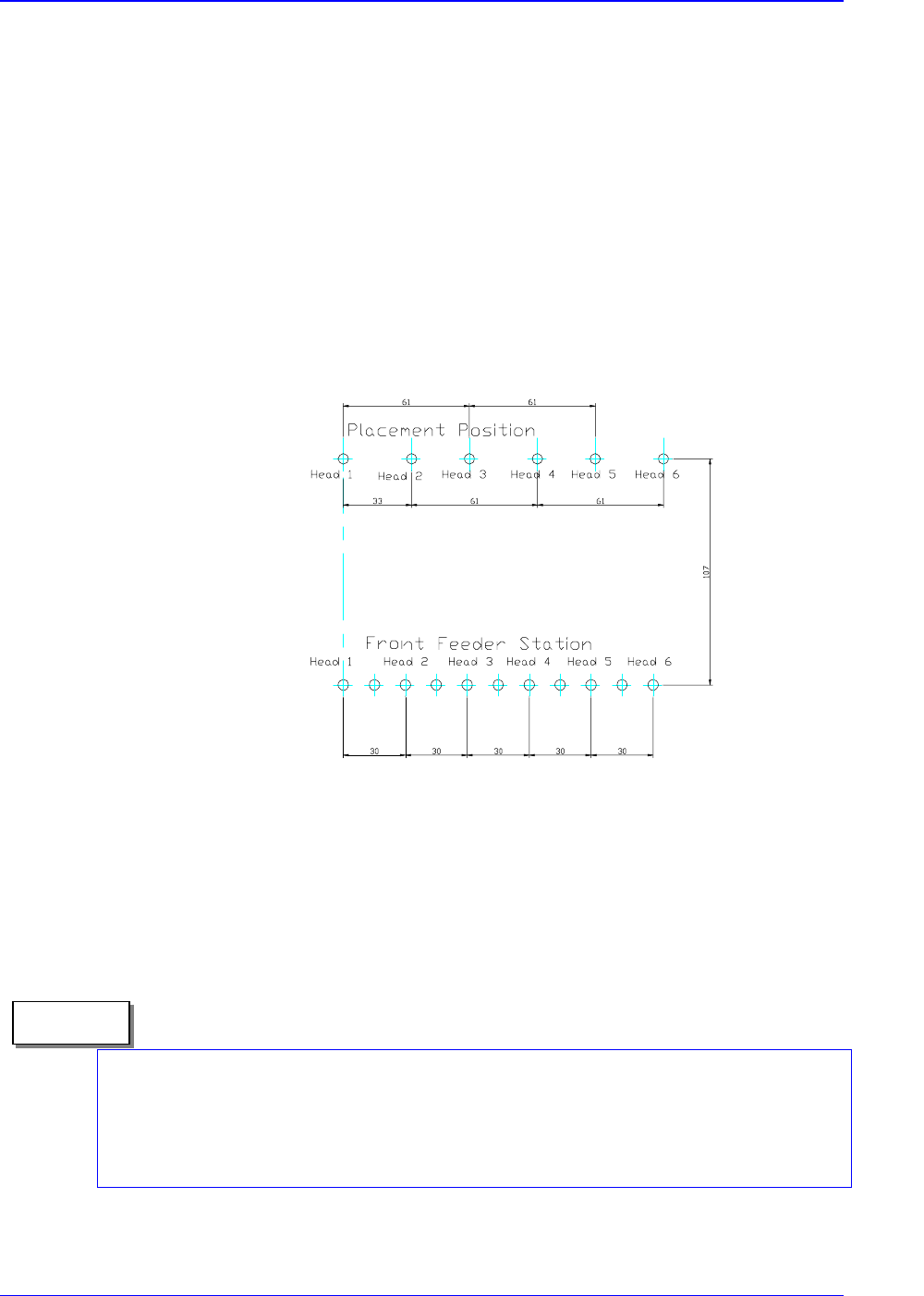
The optimum condition for the tact time is specified.
The placed Component : 1608 chip
Time Measurement
The measured time from the first pickups to return of the machine to the original
position following the final placement.(Off-line time, i.e., the time for recognizing the
fiducial mark, or PCB feed time, is excluded.)
Figure 1-2. The Summary for Measuring the Tact Time (6 Heads Simultaneous Pickups, Each
heads place)
The above speed is for the pick & place cycle time under the optimum conditions
(rounded off to 1msec). The experimental conditions is under using a very new
equipment with a taped PCB at the factory site, therefore, in actual placement, it can vary
according to the placement conditions.
Memo
Samsung Component Placer CP-45F(V)/FS Operations Manual
1-6
1.2.4.2. The pick & place cycle time for each model
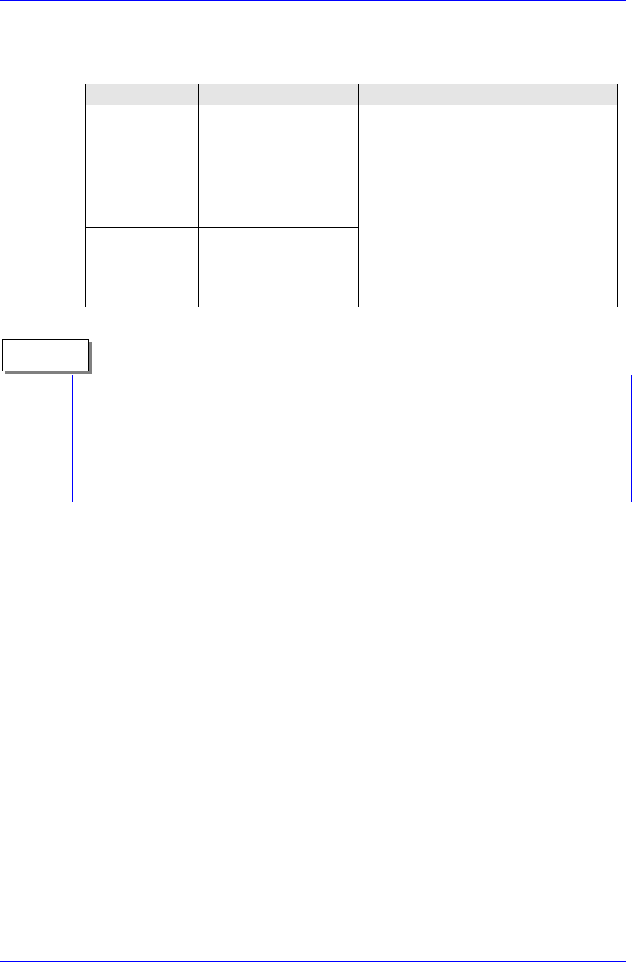
Table 1-5. The pick & place Cycle Time for Each Model
Classification CP-45FV Remarks
Chip
0.197sec / component
(1608)
QFP
0.75 sec / component
(Flying Vision)
1.6 sec / component
(Stage Vision)
Connector
0.5 sec / component
(Flying Vision)
1.6 sec / component
(Stage Vision)
Simultaneous pickups under the optimum
conditions
Note) In the case of micro chips, lower it to
a proper speed by reducing the speed or
adjusting the delay variable according to the
placement status.
.Based on the optimum condition of QFP 80
(Y100mm, 100mm)
. Based on the optimum condition of black,
same interval, symmetrical type,
(Y 100mm , X 100mm)
The above are for the pick & place cycle time under the optimum conditions (rounded-off
to 1msec). In actual placement, the conditions that determine the cycle time may vary
depending on many factors such as the type of components, size of PCB, placement
position, etc. For more detailed information, please contact our Business Department or
C/S Center.
Memo

Features and Scope of Equipment
1-7
1.3. Mechanical Specifications
1.3.1. Size and weight of the equipment
Length
Including Cover: 1,660mm
Excluding projection of Conveyor Unit: 1,502mm
Width: 1,540mm
Height
Up to the upper surface of cover: 1,408mm
Up to the upper surface of monitor: 1,760mm
Up to the upper surface of tower lamp: 1,945mm
Weight: 1,150 kg
1.3.2. Requirements for air pressure
Pressure: 4.5 ~ 5.5 kgf/㎠
Air Consumption: 150 N ℓ /min
Dry Air: air dew point of -17℃ or less
1.3.3. Environmental conditions
During operation
Temperature: +10℃ ~ +35℃
Humidity
Less than 50% RH (35℃)
Less than 90% RH (20℃)
During shipment or storage (in states other than during operation)
Temperature: -10℃ ~ +60℃
Humidity: 20% RH ~ 90% RH (non-condensation state)