operation-cp45.pdf - 第55页
Basic Configuration and Name of Each Part 2-3 2.2.2. Control part configuration F i g u r e 2 - 3 . C o n t r o l P a r t C o n f i g u r a t i o n D i a g r a m
Samsung Component Placer CP-45F(V)/FS Operations Manual
2-2
2.2. System Configuration
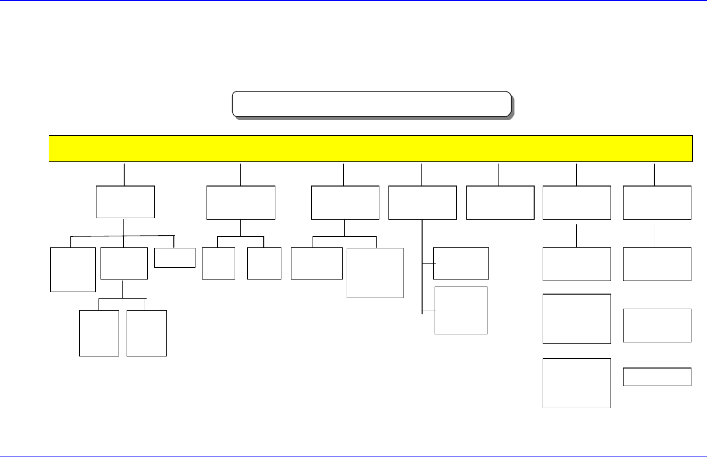
2.2.1. Mechanical part configuration
CP-45FV Mechanical Part Configuration
BODY FRAME
Mirror
Driving
Part
Side ILL.
Driving
Part
UPWARD
CAMERA
Electric Part &
COVER
35mm
CAMERA
CONTROL
BOX
45mm
CAMERA
(OPTION)
CONTROL
BOX
20mm
CAMERA
(OPTION)
COVER
FEEDER
BASE
HEAD
(6NOZZLE)
X-Y
GANTRY
X
AXIS
Y
AXIS
FLYING
CAMERA
UNIT
FIDUCIAL
CAMERA
UNIT
NOZZLE
Fixed ANC
(36POCKET)
Correct Tool
(1POCKET)
ANC
UNIT
3Stage
CONVEYOR
Driving-Motor
Adjust Width
(OPTION)
CONVEYOR
UNIT
Figure 2-2. Mechanical Part Configuration Diagram
Basic Configuration and Name of Each Part
2-3
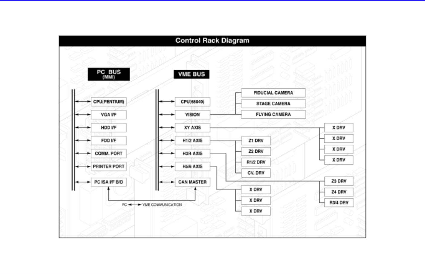
2.2.2. Control part configuration
Figure 2-3. Control Part Configuration Diagram
Samsung Component Placer CP-45F(V)/FS Operations Manual
2-4
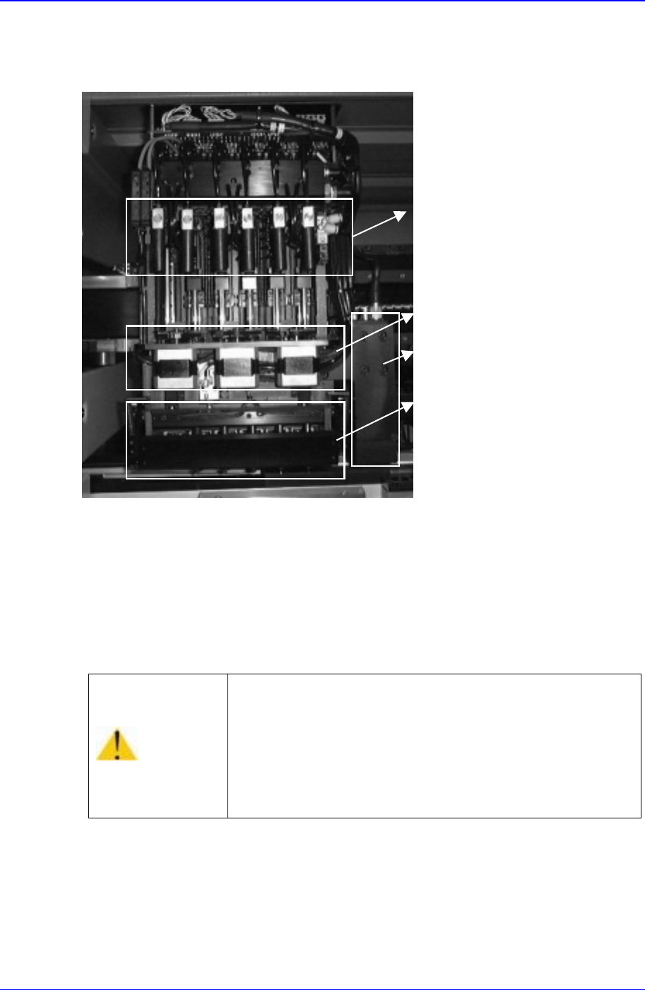
2.3. Head Assembly
2.3.1. Head assembly of CP-45F/V and CP-45FS
Figure 2-4. Head Assembly of CP-45F/V and CP-45FS
The head assembly is manufactured in one module; the module is composed of six
spindle units.
Each spindle has its own Flying vision, and adopts non-contact-type centering so that
stable operation can be performed. All spindles are arranged at regular intervals of
30.00 mm for simultaneous pickups from the tape feeder.
Warning
As the descending speed of Z axis of head is 9G,
inserting a hand under the head while the machine is in
operation could result in injury.
Do not insert a hand under the head while the machine is
in operation.
Vacuum Valve
Theta Axis Motor
Fiducial Camera
Flying Vision