operation-cp45.pdf - 第80页
Samsung Component Placer CP-45F(V)/FS Operations Manual 2-28 2.13.3. Special nozzles T able 2-9. Special Nozzles Ty p e Odd(for Odd-type components) Calibration T ool Nozzle Name TP20 TP40 CN20 Inner Diameter - - ψ 2.0 O…
Basic Configuration and Name of Each Part
2-27
2.13.2. General nozzles
Nozzles should be properly selected according to the type and size of the components.
The nozzles generally used in the CP-45FV model are identical. Black nozzles are
occasionally used for some components in the flying vision unit and the upward vision
unit.
The nozzle should be selected correctly since it may cause improper adsorption, or
improper placement problems. The nozzles generally used are shown in “Table 2-7“. For
accurate pick & place, a proper nozzle should be selected in reference to the minimum
suction area of each component.
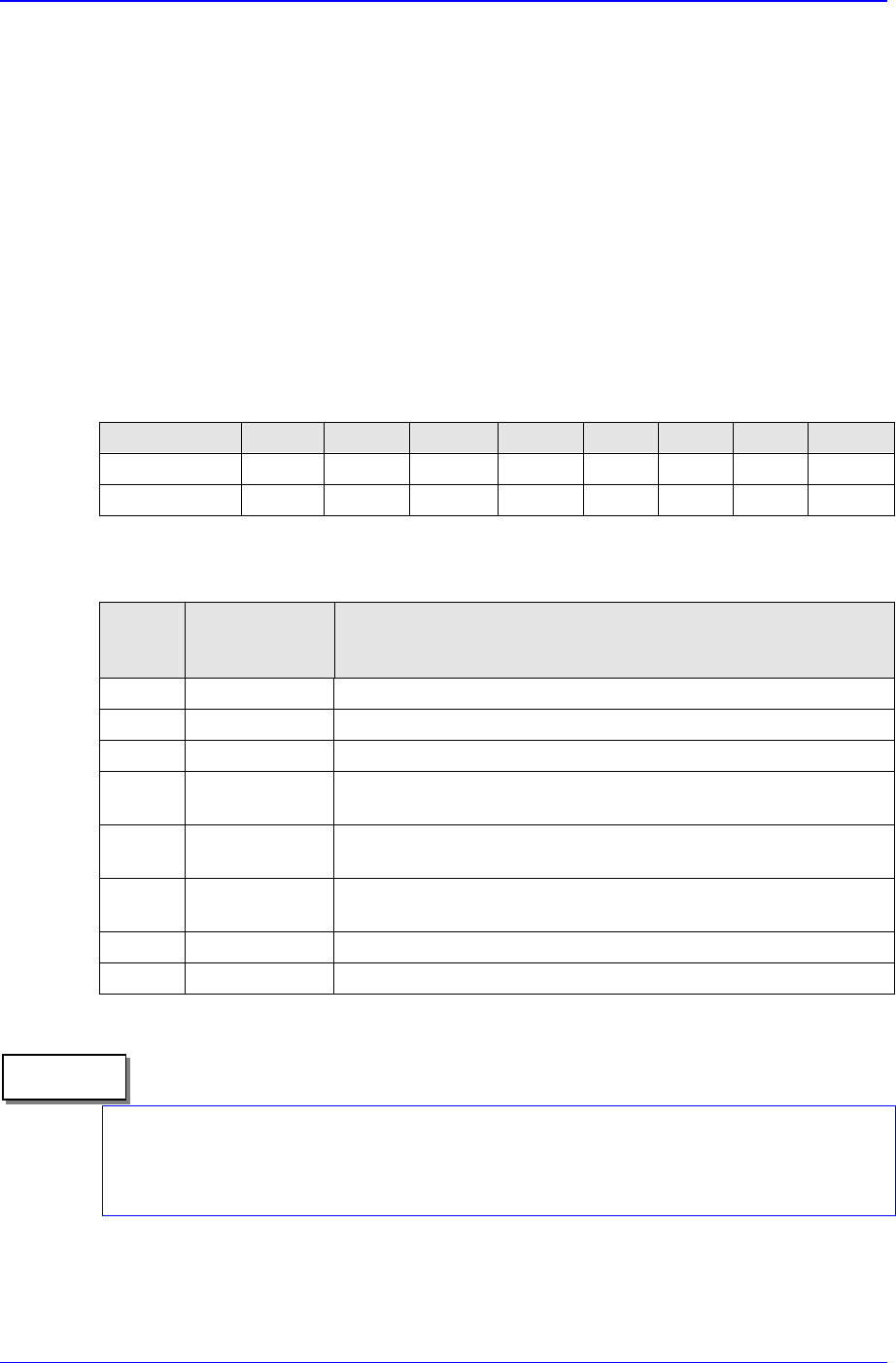
Table 2-7. General Nozzles
Nozzle name
TN-03 TN-04 TN-065 TN-14 TN-22 TN-40 TN-75 TN-110
Outer diameter
Φ 0.8 Φ 0.75 Φ 1.2 Φ 2.2 Φ 3.6 Φ 6.2 Φ 9.0 Φ 12.7
Inner diameter
Φ 0.28 Φ 0.38 Φ 0.65 Φ 1.4 Φ 2.2 Φ 4.0 Φ 7.5 Φ 11.0
Table 2-8. Examples of Applying General Nozzles to Components
Nozzle
name
Minimum
component
width
Major component types
TN-03 0.3 ~ 1.5 0603,1005 only
TN-04 0.5 ~ 1.25 1005, 1608, 2012,3216, SOT(Molded part 0.8 X 1.6)
TN-065 0.8 ~ 2.5 1608, 2012,3216, MELF(Molded part 1.2 X 2.0), SOT23
TN-14 2.5 ~ 4.0
Aluminum electrolytic capacitor(small), Tantalum capacitor,
Trimmer
TN-22 4.0 ~ 7.0
Aluminum electrolytic capacitor(medium), SOP(Narrow), SOJ,
Connector
TN-40 7.0 ~ 10.0
Aluminum electrolytic capacitor(large), SOP(Wide), TSOP, QFP,
PLCC, SOJ, Connector
TN-75 10.0 ~ QFP(medium), PLCC(medium)
TN-110 20.0 ~ QFP(large), PLCC(large)
Our company can supply various nozzle types are not included in “Table 2-7“ to satisfy
the user requirement. For inquiries on special nozzles, please contact our Business
Department or C/S Center.
Memo
Samsung Component Placer CP-45F(V)/FS Operations Manual
2-28
2.13.3. Special nozzles
Table 2-9. Special Nozzles
Type Odd(for Odd-type components) Calibration Tool
Nozzle Name TP20 TP40 CN20
Inner Diameter - -
ψ 2.0
Outer Diameter - -
ψ 15.4
Pickup Area
2× 10 4× 12
ANC hole Large Large Large
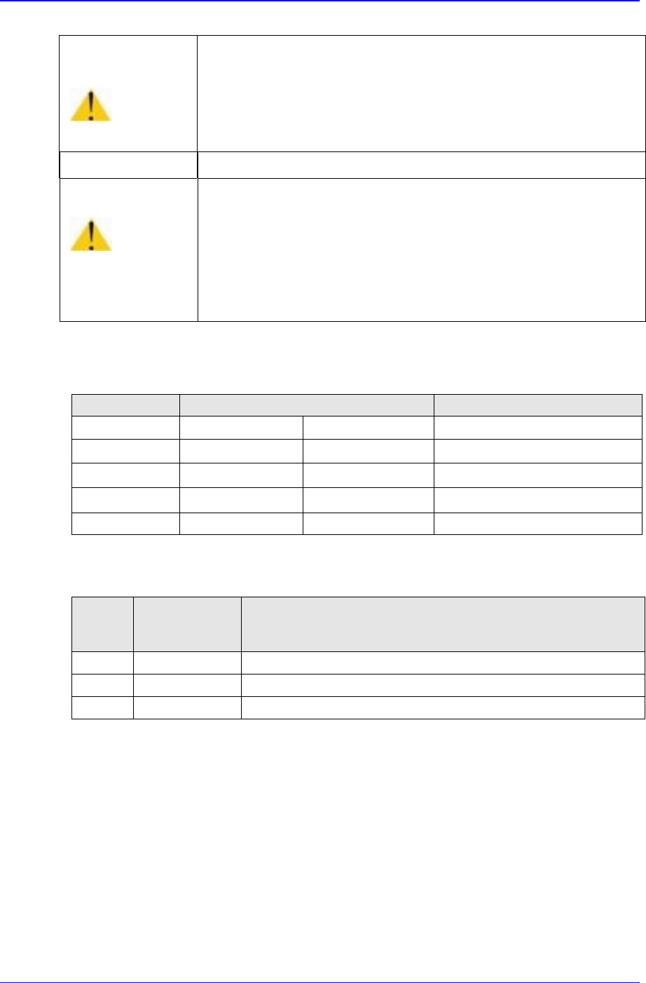
Table 2-10. Examples of Applying Special Nozzles to Components
Nozzle
name
Minimum
component
width
Major component types
TP20 2.5 ~ Connectors for which vacuum adsorption is possible
TP40 4.5 ~ Connectors for which vacuum adsorption is possible
CN20 - Tool for Calibration
Caution
This table simply means that the conventional nozzle of 10-
hole ANC has the same inner and outer diameters as those of
the nozzle of 20-hole ANC. It does not mean that they can be
used interchangeably. Only nozzles listed in the above table
should be used for each ANC type.
Caution
The machine might operate irregularly if standard regular
nozzles are not used.
1. Failure of nozzle change
2. Dislocation of nozzle during operation
3. Failure of component pick up
Be sure to use standard regular nozzles.
Basic Configuration and Name of Each Part
2-29
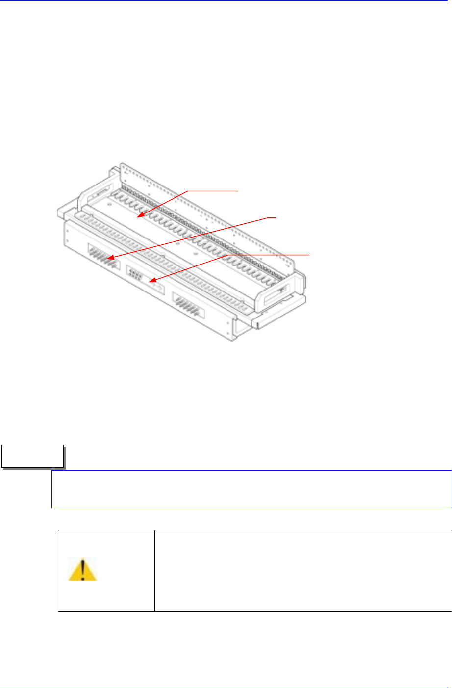
2.14. Feeder Station Part
Components can be supplied during operation by placing the component supply
device on the feeder base. The part can be used by installing ANC, tape feeder, stick
feeder, and stack stick feeder, and on the rear side single-tray feeder and multi-tray
feeder can be installed.
The ANC, air pressure supply coupling for the stack stick feeder, and power
connector are situated on the connector panel at the front side.
Figure 2-19. Feeder Station Part
Speed control of a multi-cylinder is possible since a speed control valve is protruded. The
multi-cylinder (feeder driving cylinder) is located at the lower side of the feeder base, and
is a multiple-drive cylinder driving the lever of a feeder by the piston load.
The both end slot of the front and rear feeder base (mechanical: number 1 and 52;
electrical: number 1 and 76), only the 8mm tape feeders are available.
Caution
If the nut is not locked after adjusting the Speed Control
Valve, the speed might change.
Be sure to lock the nut after adjusting the Speed Control
Valve.
Connector panel
Feeder base
Speed control valve
Memo