operation-cp45.pdf - 第306页
Samsung Component Placer CP-45F(V)/FS Operations Manual 15-20 <Fly Camera Offset> button Calibrates the offset of the fly camera. <Head Offset> button Calibrates the offset of the head. <Camera Offse…
Sys.Setup Command
15-19
Head2: Selects Head2.
Head3: Selects Head3.
Head4: Selects Head4.
Head5: Selects Head5.
Head6: Selects Head6.
<Move> button
Moves the XY, Z, and R axes to the device selected in <Device>. At this time, the
edit box corresponding to the position to be read must be clicked on by a mouse.
<Get> button
Reads in the current position of the XY, Z, and R axes of the device selected in
<Device>.
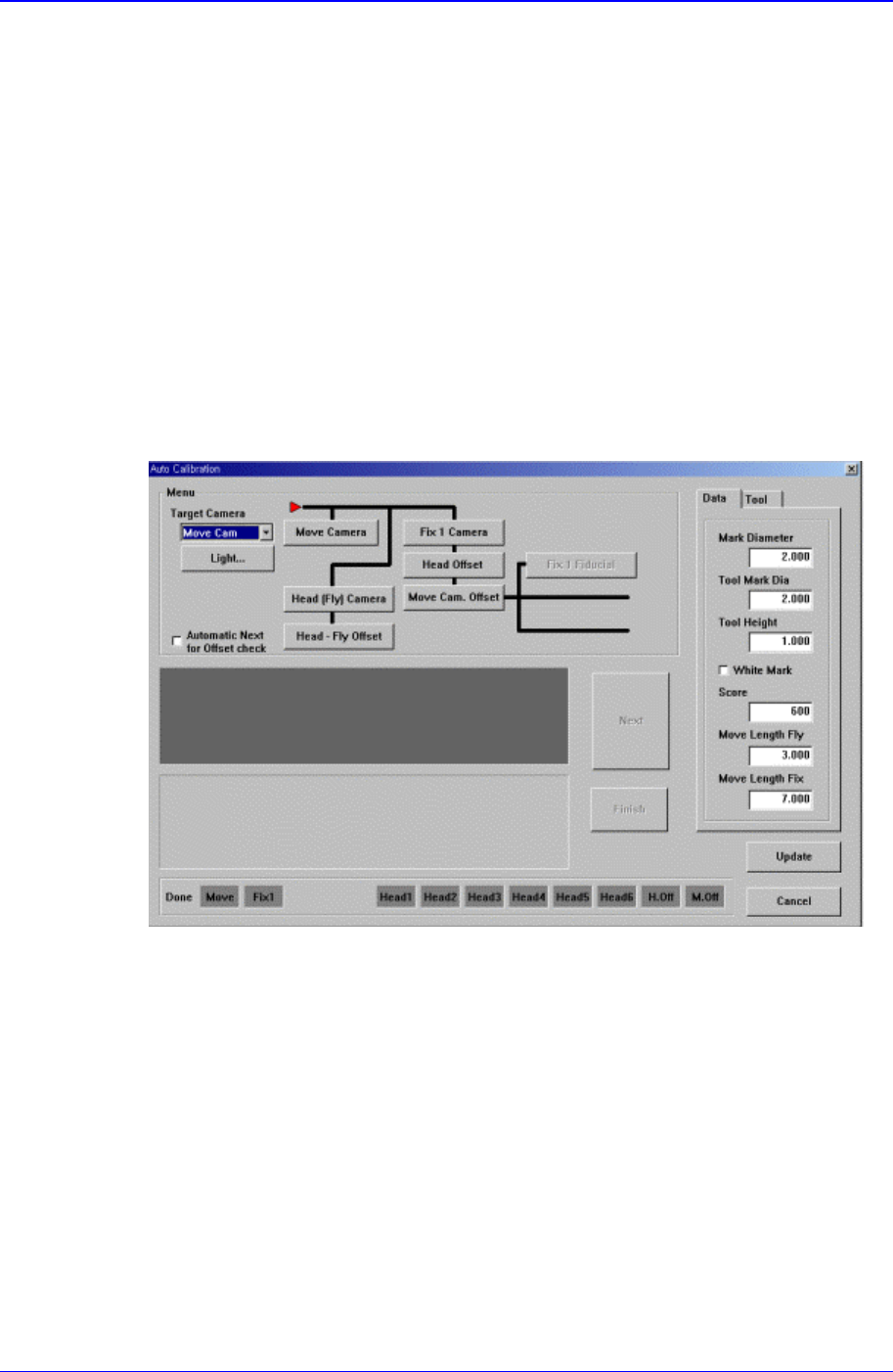
<Calibration> button
Performs the camera calibration function. When this button is clicked on, the
following screen is displayed.
<Camera> combo box
Select the camera to set light value.
<Light…> button
Set the light value for the selected camera..
<Menu> group
Select the items to calibrate.
<Fiducial Camera> button
Calibrates the move camera..
<Fix Camera> button
Calibrates the fix camera.
<Fly Camera> button
Calibrates the fly camera.

Samsung Component Placer CP-45F(V)/FS Operations Manual
15-20
<Fly Camera Offset> button
Calibrates the offset of the fly camera.
<Head Offset> button
Calibrates the offset of the head.
<Camera Offset> button
Calibrates the offset of the fix camera.
<Mark Dia (Sheet)> edit box
Set the diameter of the calibration tool for the move camera.
<Tool Mark Dia> edit box
Set the diameter of the calibration tool for the fix camera.
<Tool Height> edit box
Set the length of the calibration tool.
<White Mark> check box
In the case of white mark, check it.
<Score> edit box
Set the recognition value to recognize the calibration tool.
<Move Length Head Cam> edit box
Set the distance to move the calibration tool for the move camera.
<Move Length Fix Cam> edit box
Set the distance to move the calibration tool for the fix camera.
<BUT Up/Downl> button
Moves up/down the BUT(Back Up Table).
<Download cam. info> button
Downloads the camera data to the equipment.
<Move to home pos.> button
Moves the device selected in <Device> to Home.
<Mirror open / close> button
Opens or closes the mirror.
<Device> combo box
Select the XY and Z axes.
Move Cam: Selects Teaching Camera.
Head1: Selects Head1.
Head2: Selects Head2.
Head3: Selects Head3.
Head4: Selects Head4.
Head5: Selects Head5.
Head6: Selects Head6.
<Move to fix 1 Cam.> button
Moves the device selected in the Device to the position of the fix camera.
<Z axis Up/Down> button
Sys.Setup Command
15-21
Lowers the Z axis of the head selected in the Device.
<No real motion> check box
Determines whether to really execute the nozzle pick/put motion or to manipulate
the data only. When it is checked, only the data is manipulated.
<Put all nozzle> button
Puts all nozzles in the head.
<Put> button
Puts the nozzle in the head selected in the Device.
<Pick> button
Picks the calibration tool with the head selected in the Device.
<Update> button
Saves the set data and closes the screen.
<Cancel> button
Ignores the set data and closes the screen.
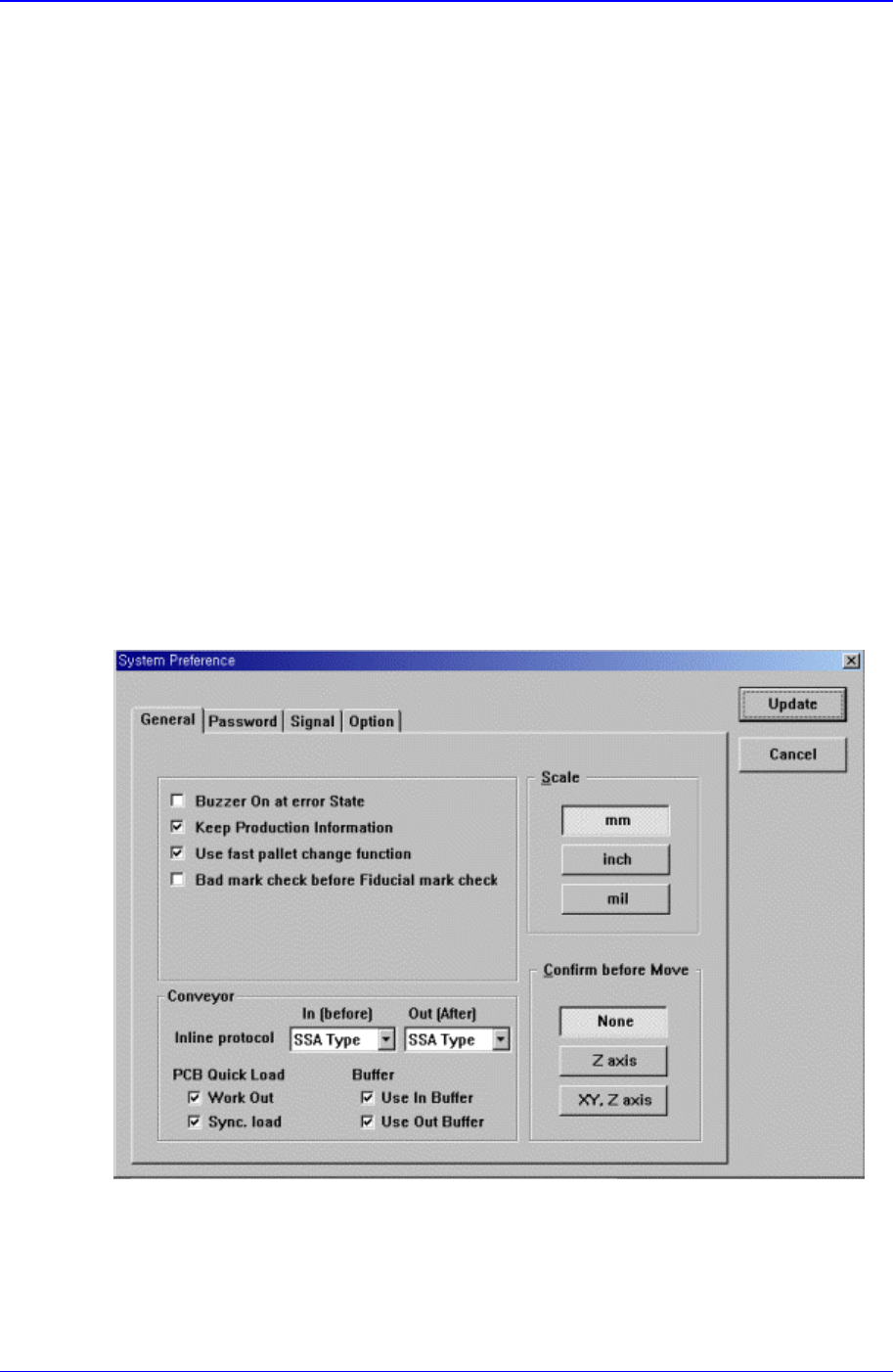
15.9. Pref. [F9]
Sets various options needed for equipment operation.
When this button is clicked on, the following dialog box is displayed.
Figure 15-11. “Sys. Setup : System Preference - General” dialog box
<General> option button
Sets various options used in the MMI program.
<Skip the erroneous Component> check box
If this button is checked, when a component fails to be picked up during