operation-cp45.pdf - 第52页
Samsung Component Placer CP-45F(V)/FS Operations Manual 1-14 1.5.5. Connections with peripheral units 1.5.5.1. Signals and interface T able 1-6. Signals and Interface Signal Item Specifications Remark PIN No.1: (+)Input …
Features and Scope of Equipment
1-13
arranged individually on the teaching box, and there is an LED for indicating the button
presently being used. For more detailed description on the operation of the teaching box,
please refer to “3.3 Button Manipulation of Teaching Box (page 3-5)”.
1.5.3.3. Mouse
The mouse facilitates the operation of Windows and MMI.
1.5.3.4. Monitor
The CP-45F/V and the CP-45FV has a color monitor for showing how the production
program is created and edited and how the system is operated.
Also the CP-45F/V and the CP-45FV has color monitors for camera teaching.
1.5.4. Number of data that can be handled by MMI
Number of steps placed: 3,000 Step (maximum)
Number of programs PCB production: more than 1,000 (maximum)
Number of component data: 200 (maximum)
Number of feeder data
Tape Feeders: 104
Stick Feeders: 100 Lane
Matrix Tray Feeder: 3
Number of component marks: 2 per component
Number of PCB marks: 2 per component
Caution
If two monitors are placed side by side, the life span of
monitors could be affected.
Leave an interval of 30 cm or more between two monitors.
Samsung Component Placer CP-45F(V)/FS Operations Manual
1-14
1.5.5. Connections with peripheral units
1.5.5.1. Signals and interface
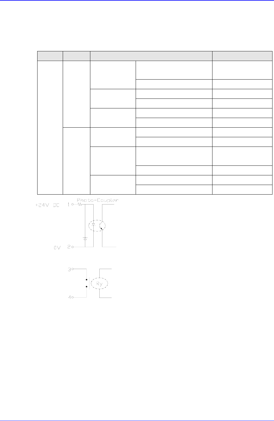
Table 1-6. Signals and Interface
Signal Item Specifications Remark
PIN No.1: (+)Input Signal Less than
24 V/10mA
Busy Input(In)
PIN No.2: (-) Ground
PIN No.3: Contact output
Board Available
Output(Out)
PIN No.4: Contact output
AMP 206043-1 Machine Side
From
Next
M/C
Connector
AMP 206044-1 External Connection
PIN No.1: Contact output
Busy
Output(Out)
PIN No.2: Contact output
PIN No.3: (+) Input Signal Less than
24 V/10mA
Board Available
Input(In)
PIN No.4: (-) Ground
AMP 206043-1 Machine Side
In-Line
Signal
From
Pervious
M/C
Connector
AMP 206044-1 External Connection
Figure 1-4. Interface
1.5.5.2. Connectors
Socket for tray feeder: 25 pin D-sub
Socket for RS232C: 25 pin D-sub
Socket for printer: 25 pin D-sub
Teaching Box Connector: HR10A-7R-6S
Connector for ANC: 6 Pin Circular Type
Connector for Stick feeder: 6 Pin Circular Type
Basic Configuration and Name of Each Part
2-1
Chapter 2. Basic Configuration and Name
of Each Part
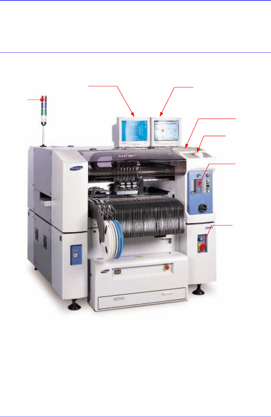
2.1. Exterior (Name of Each Part)
Figure 2-1. Equipment Exterior (Front View)
Programming Monitor
K
eyboa
r
d
Mouse
Teaching Box
Isolation Switch
Teaching Monitor
Signal Towe
r