operation-cp45.pdf - 第180页
Samsung Component Placer CP-45F(V)/FS Operations Manual 11-26 Displays the type of the feeder supplyi ng components. The types of feeders are as follows. 8mm Tape: Supply by 8mm Tape Feeder. 12mm Tape: Supply by 12mm Tap…
PCB Edit Command
11-25
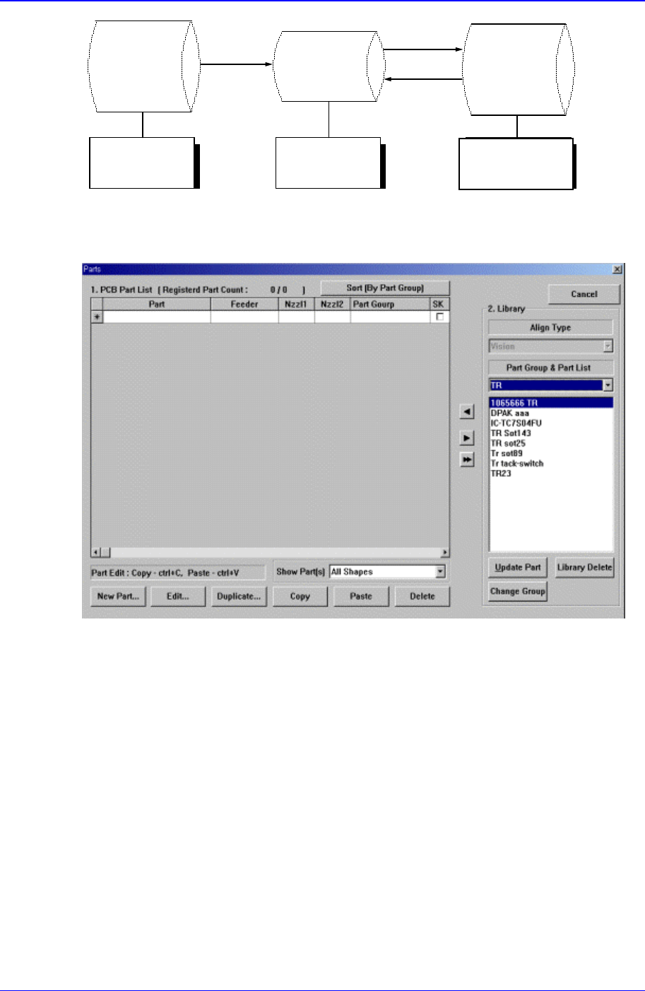
Standard
Part DB
PCB Part
Local
Part DB
Figure 11-18. Relationship between component DBs
When the <Part> command is selected, the initial screen is as follows.
Figure 11-19.”Parts” dialog box
<1. PCB Part List> group
Display a list of currently registered components.
<Part> column
Displays the component name.
<Feeder> column
Create
New
p
art
Save
Copy
Applied to
all PCBs
Controlled by
each PCB
Controlled by
each equipment

Samsung Component Placer CP-45F(V)/FS Operations Manual
11-26
Displays the type of the feeder supplying components. The types of feeders are
as follows.
8mm Tape: Supply by 8mm Tape Feeder.
12mm Tape: Supply by 12mm Tape Feeder.
16mm Tape: Supply by 16mm Tape Feeder.
24mm Tape: Supply by 24mm Tape Feeder.
32mm Tape: Supply by 32mm Tape Feeder.
44mm Tape: supply by 44mm Tape Feeder.
56mm Tape: Supply by 56mm Tape Feeder.
32mm Adhensive: Supply by 32mm Adhesive Tape Feeder.
Belt Stack Stick: Supply by Belt Stack Stick Feeder.
Vibration Multi Stick: Supply by Vibration Multi Stick Feeder.
Belt Multi Stick: Supply by Belt Multi Stick Feeder.
Single Tray: Supply by Single Tray Feeder.
FW-20F: Supply by 20-stage Tray Feeder.
FW-20S: Supply by 20-stage Tray Feeder.
FW-12M: Supply by 12-stage Tray Feeder.
<Nozzle1> column
Displays the nozzle that pick up components. The nozzle types are as follows.
NP20:
NP40:
TNSQ:
TN14:
TN22:
TNDSQ:
TN40:
TN75:
TN110:
<Nozzle2> column
Displays the auxiliary nozzle that adsorbs components. When the main nozzle
can not be used, the auxiliary nozzle is used. The types of auxiliary nozzles are
the same as the main nozzle.
<Part Group>
Displays the component Part Group.
<SK> check box
When it is checked, this part is skipped during placing.
<New Part…> button
Registers new component. When this button is clicked on, the following dialog box is
displayed.
PCB Edit Command
11-27
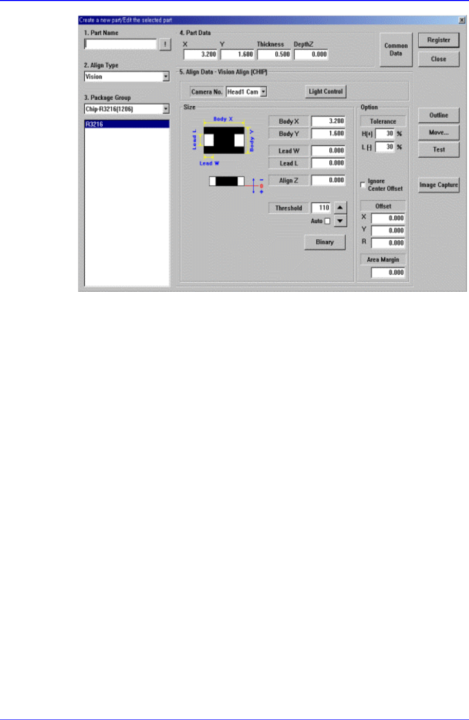
Figure 11-20. “Create a new part/Edit the selected part” dialog box
<1. Part Name> edit box
Set the component name.
<2. Align Type> combo box
Select the align type.
<3. Package Group> combo box
Select the component group.
<Package List> list box
Displays the component data list selected in <2. Align Type> and <3. Package
Group>.
<4. Part Data> group
Set the data including the component size.
<X> edit box
Set the component size in X direction.
<Y> edit box
Set the component size in Y direction.
<Z> edit box
Set the height(thickness) of the component.
<DepthZ> edit box
Set the depth of the groove on top of the component. Unless warranted by a
special purpose, set to “0”.
<Skip> check box
If you want to skip the corresponding component, check the check box.
<5. Align Data> group