operation-cp45.pdf - 第106页
Samsung Component Placer CP-45F(V)/FS Operations Manual 4-4 button. Up/Down can be performed by selecting the <Place Stop. U/D> item from the list and then repeatedly pressing the space key . 4.5. Board Detection S…
Sensor Detection Functions
4-3
3. The back-up table is moved up and down following the selection of <But Up/Down>
button. Up/Down can be performed by selecting the Up/Down item from the list and
then repeatedly pressing the space key.
4.4. Up/Down of Place Stopper
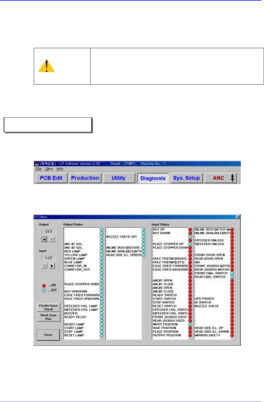
1. Select <Diagnosis> from the MMI main menu tool-bar, and select “<I/O>(F2)” from
the sub menu tool-bar on the left displayed.
“I/O Status” dialog box is shown on the screen. If the box is already shown, it is not
necessary to do it again.
Figure 4-3. “Manual Control” dialog box
2. In order to move the place stopper, double-click on the <Place Stop. U/D> button in
the <Output> list box, or click on the adjacent round button at the side.
3. The ing stopper is moved up and down following the selection of <Place Stop. U/D>
Caution
Be sure to remove any foreign substance on the BUT and
obstruction before manipulating the BUT.
Otherwise, the conveyor might be damaged.
Operational procedure
Samsung Component Placer CP-45F(V)/FS Operations Manual
4-4
button. Up/Down can be performed by selecting the <Place Stop. U/D> item from
the list and then repeatedly pressing the space key.
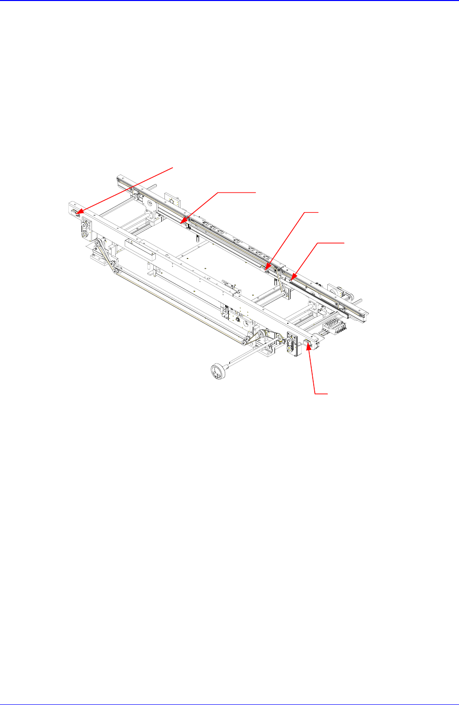
4.5. Board Detection Sensor
There are five board detection sensors installed on the PCB take-in and take-out paths of
the conveyor.
Figure 4-4. Installing Position of PCB Detection Sensors
The positions and functions of each sensor are as follows:
Input Sensor: Detects take-in of PCB into this equipment from the previous process.
Wait Sensor: Detects PCB in the Wait buffer (at the wait position).
Place Sensor: Detects PCB in the place buffer (at the placement position).
Quick-Load Sensor: Detects PCB completed placement so that the PCB in the wait
buffer can be loaded quickly.
Output Sensor: Detects PCB taken out from the equipment.
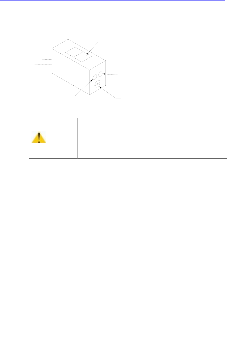
The conditions for detection may vary depending on the installation method, distance,
and angle and location of each sensor as well as due to dust, external light, shape, and
color of the board. Therefore, sensitivity of a sensor should be adjusted by using the
actual board that will be used. Sensitivity of a board detection sensor is adjusted by
turning a control screw that is attached to each sensor with no PCB present until the green
Place Sensor
Wait Sensor
Output Sensor
Input Sensor
Quick Load Sensor
Sensor Detection Functions
4-5
LED is lighted. The case of no lighting indicates an unstable state.
Sensitivity is then adjusted with a PCB until the red and green LED's are lighted. The
case of only red LED lighted indicates an unstable state.
Figure 4-5. Sensor Adjustment
Warning
Adjusting the sensor or correcting an error while the
machine is ready could result in personal injury.
Be sure to adjust the sensor or correct an error in the stop
status (idle mode) after canceling the ready status.
Sensor Window
Green LED
Red LED
Sensitivity Adjusting Screw