operation-cp45.pdf - 第297页
Sys.Setup Command 15-1 1 T o use the selected tray feeder unit, set th e feeder base unit and slot taken up by the corresponding tray . <Feeder Base> combo box Select the feeder base. In the case of th e CP45FV m…
Samsung Component Placer CP-45F(V)/FS Operations Manual
15-10
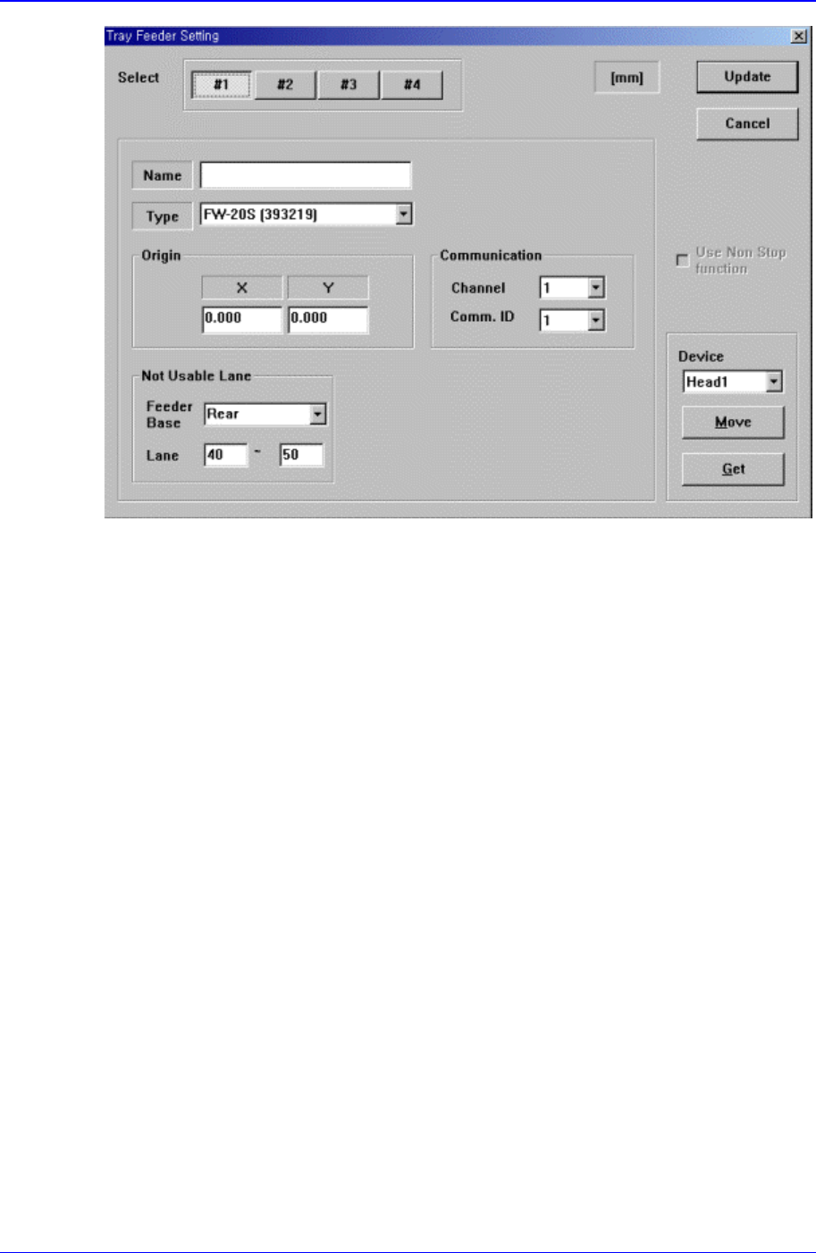
Figure 15-8. “Sys. Setup : Tray Feeder Setting” dialog box
<Select> option button
Select the tray feeder unit. Available tray feeder units are 1 – 4.
<Name> edit box
Set the name of the selected tray feeder unit.
<Type> combo box
Select the type of the set tray feeder unit. Available types are as follows.
Single Tray: Tray to be installed on the feeder base.
FW-20F: Tray consists of 20 step Palette, it communicates with the equipment
through RS-232C.
FW-20S: Tray consists of 20 step Palette, it communicates with the equipment though
RS-232C.
NONE: Means no tray is installed.
<Origin> group
Set the origin of the selected tray feeder unit. This origin is the offset value from the
equipment origin.
<Communication> group
Set the data related to RS-232C communication.
<Channel> combo box
Select the RS-232C communication channel. Two channels are available for the
equipment.
<Comm. ID> combo box
Select the communication ID. Available IDs are 1 – 3.
<Not Usable Lane> group

Sys.Setup Command
15-11
To use the selected tray feeder unit, set the feeder base unit and slot taken up by the
corresponding tray.
<Feeder Base> combo box
Select the feeder base. In the case of the CP45FV model, available feeder bases
are Front( front Feeder Base), and Rear( rear Feeder Base).
<Lane> edit box
Set the slot of the feeder base.
<Fiducial> button
At the moment, it does not have a function.
<Device> combo box
To move or to read in the positions of the XY and Z axes, select the corresponding
device. Available devices are as follows.
Move Cam: Selects Teaching Camera.
Head1: Selects Head1.
Head2: Selects Head2.
Head3: Selects Head3.
Head4: Selects Head 4.
Head5: Selects Head5.
Head6: Selects Head6.
<Move> button
Moves the XY and Z axes with the device selected in <Device>. At this time, the edit
box corresponding to the position to move to must be clicked on with a mouse.
<Get> button
Reads in the XY and Z axis of the device selected in <Device>. At this time, the edit
box corresponding to the position to be read must be clicked on with a mouse.
<Update> button
Transmits the set data to the equipment and closes the dialog box.
<Cancel> button
Ignores the set data and closes the dialog box.
15.7. Dump [F7]
Sets the data on the dump box where the picked up components are dumped.
When this button is clicked on, the following dialog box is displayed..
Samsung Component Placer CP-45F(V)/FS Operations Manual
15-12
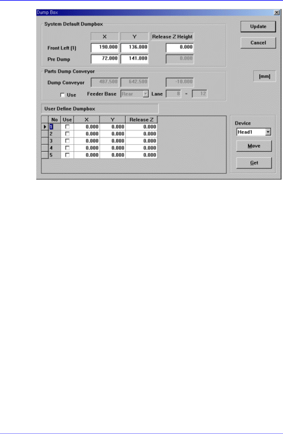
Figure 15-9. “Sys. Setup : Dump Box” dialog box
<System Default Dumpbox> group
Set the data on the system dump box provided by the System as a default. 2 system
dump boxes are installed on the conveyor guide located close to the front of the
equipment as a default.
<Position X, Y – Front Left(1)> edit box
Set the position of the system dump box 1(Located on the left of the conveyor
guide).
<Position X, Y – Pre Dump> edit box
Set the position on which the head block stops before dumping.
<Release Z Height> edit box
Set the Z axis height of the head at the time of dumping.
<Part Dump Conveyor> group
The position of the part dump conveyor is set to default. If the position of the part
dump conveyor is needed to change, check <Use> check box and teach its new
position.
<User Define Dumpbox> group
Set the data on the user dump box installed by the user. The maximum number of
dump boxes that can be set by the user is 5.
<Grid - No> column
Displays the user dump box number.
<Grid - Use> column
Set whether to use the corresponding user dump box or not.
<Grid - X> column