operation-cp45.pdf - 第162页
Samsung Component Placer CP-45F(V)/FS Operations Manual 11-8 Enter the number of Array PCBs as follows. X=3 Y=2 <Count Direction> option button group Select a method of numbering Array PCBs. XD i r 인경 우 1 2 3 4 5…
PCB Edit Command
11-7
corresponding device. Available devices are as follows.
Move Cam: Selects Teaching Camera.
Head1: Selects Head1.
Head2: Selects Head 2.
Head3: Selects Head 3.
Head4: Selects Head 4.
Head5: Selects Head 5.
Head6: Selects Head 6.
Beam: Selects Beam.
<Move> button
Moves the XY and R axes to the device selected in <Device>. Before
executing “Move”, the cell in the grid corresponding to the desired position
must be clicked on with a mouse.
<Get> button
Reads in the current position of the XY, and R axes of the device selected in
<Device>. Before executing “Move”, the cell in the grid corresponding to the
desired position must be clicked on with a mouse.
<3. Sequence> group
Select the Array PCB operation method.
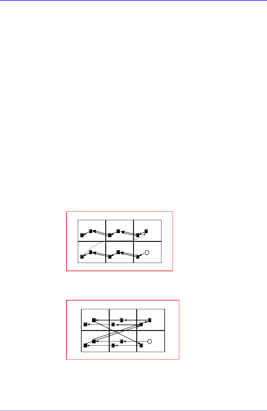
<By PCB> option button
A method of completing one Array PCB operation and then executing the
next Array PCB operation.
13
4
2
56
<By Point> option button
A method of completing an operation cycle to all array PCBs and then
executing the next cycle operation.
13
4
2
56
<4. Set Array (Regular Type)> group
Initializes the Array PCB. This function sets the offset value of each Array PCB
automatically when the arrangement of array PCB is regular.
<Number> edit box group
Samsung Component Placer CP-45F(V)/FS Operations Manual
11-8
Enter the number of Array PCBs as follows.
X=3
Y=2
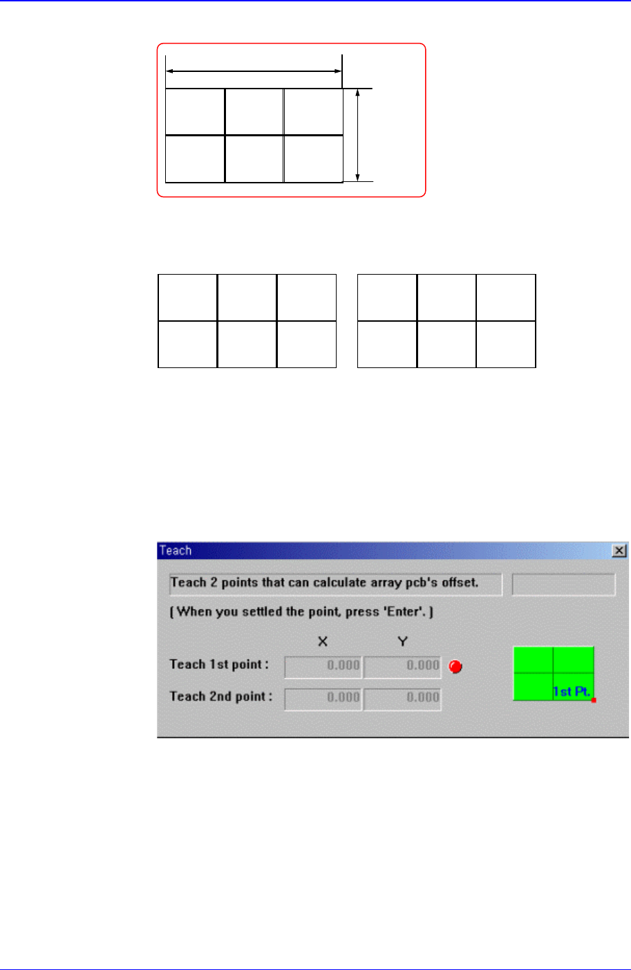
<Count Direction> option button group
Select a method of numbering Array PCBs.
XDir
인경우
123
4
56
YDir
인경우
135
2
46
<Offset> edit box group
This value is used to set the offset value of the origin of Array PCB
automatically.
<Teach> button
This button is used to teach the offset value of Array PCB in the same way as
teaching the PCB size. When this button is clicked on, the following screens
are displayed in succession.
Figure 11-9. Screen showing first point teaching for Array PCB Offset
Teach the origin of Array PCB 1. When the “Enter” key is pressed after
teaching, the following screen is displayed.
When the X Direction is selected When the Y Direction is selected

PCB Edit Command
11-9
Figure 11-10. Screen showing second point teaching for Array PCB Offset
Teach the origin of the Array PCB on the position that can determine the
offset. When the Enter key is pressed after teaching, the following screen is
displayed.
Figure 11-11 Screen showing completion of Array PCB Offset Teaching
Press the Enter key to complete the Array PCB offset value teaching
operation.
<Apply> button
Automatically creates Array PCB data with the value set in this group
<5. Add Value> group
Set the values of X, Y, and R to be added to the grid line of the <1. Array> group.
When the Add button is clicked on after setting the desired values, the values
are added to the corresponding grid lines.
<OK> button
Saves the edited data and closes the screen..
<Cancel> button
Closes without saving the edited data.
<Fiducial Mark…> button
If there is a fiducial mark on the PCB, set the position of the fiducial mark and mark
data. When this button is clicked on, the following dialog box is displayed.