operation-cp45.pdf - 第185页
PCB Edit Command 1 1-31 <Paste> button Pastes the copied part data to the Part list box. <Delete> button Deletes the part selected in the Part list box. <2. Library> group Display the component li…
Samsung Component Placer CP-45F(V)/FS Operations Manual
11-30
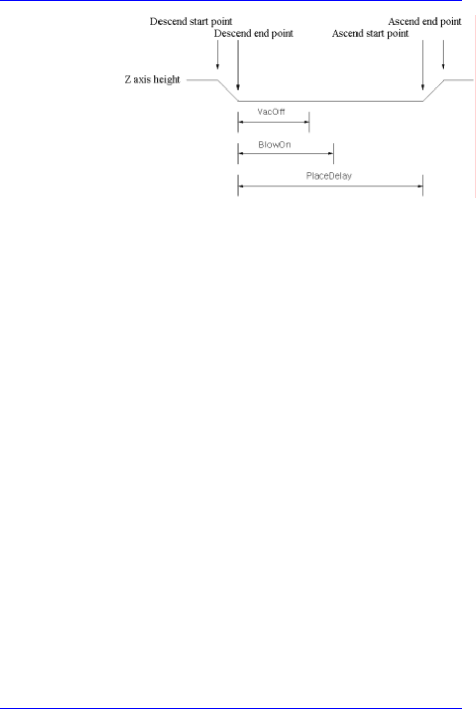
Figure 11-22. Flowchart of “Delay Time during Placement”
<Speed> group
Set the speed for each axis during pickups, placement, and dumping
operations. The speeds are as follows, and the profile of each moving speed
is set in the system.
1- Fastest: The fastest speed.
2- Fast: Fast speed.
3- Middle: Middle speed.
4- Slow: Slow speed.
5- Slowest: The slowest speed.
<XY> combo box: Select the speed for XY axis
<R> combo box: Select the speed of R axis.
<Z Pick Down> combo box: Select the speed for Z axis when the head is
lowered for component pickups.
<Z Pick Up> combo box: Select the speed for Z axis when the head is
ascending after component pickups.
<Z Place Down> combo box: Select the speed for Z axis, when the head is
lowered for placement.
<Z Place Up> combo box: Select the speed for Z axis, when the head is
ascending after placement.
<Register> button
Adds the set component data to the PCB part list.
<Close> button
Closes the dialog box.
<Edit…> button
Edits the selected component data.
<Duplicate…> button
Copies the selected component data. At this time, new component name must be
set.
<Copy> button
Copies the part data selected from the Part list box.

PCB Edit Command
11-31
<Paste> button
Pastes the copied part data to the Part list box.
<Delete> button
Deletes the part selected in the Part list box.
<2. Library> group
Display the component list of the Local Part DB managed by the equipment.
<Align Type> combo box
Select the align type of the component to be displayed. Available align types are
as follows.
None: No alignment.
Chuck: Alignment by the Chuck.
QA: Alignment by the Quad Aligner.
CA: Alignment by the Cyber Optics.
Vision: Alignment by the Vision Camera.
<Part Group> combo box
Select the group of component to be displayed. Available component groups are
as follows.
( CHIP-Circle:, CHIP-Rect:, Melf:, TR:, Trimmer:, Hemt:, SOP:, SOJ:, SOP2:,
SOJ2:, QFP:, PLCC:, Connector-1:, Connector-2:, User IC:, BGA: )
<Part List> list box
Displays the component data list of the data selected in <Align Type> and
<Part Group>.
<Update Part> button
After adding a New Part, use it to add the New part to the Local DB.
<Change Group> button
Changes the group of the selected part from current part group to another group.
<Library Delete> button
Deletes the component data selected in <Part List> from the Local Part DB.
<Copy to PCB Part>
button
Copies the component data selected in <Part List> of <2. Library> group to <1. PCB
Part List> group.
<Copy to Local Part DB>
button
Copies the component data selected in the <1. PCB Part List> group to the Local Part
DB.
<Copy All to Local Part DB>
button
Copies all component data in the <PCB Part List> group to the Local Part DB.
<Cancel> button
Cancels all edited data.
Caution - If you move to another screen while editing the “Part” dialog box, the edited
data is saved automatically.
Samsung Component Placer CP-45F(V)/FS Operations Manual
11-32
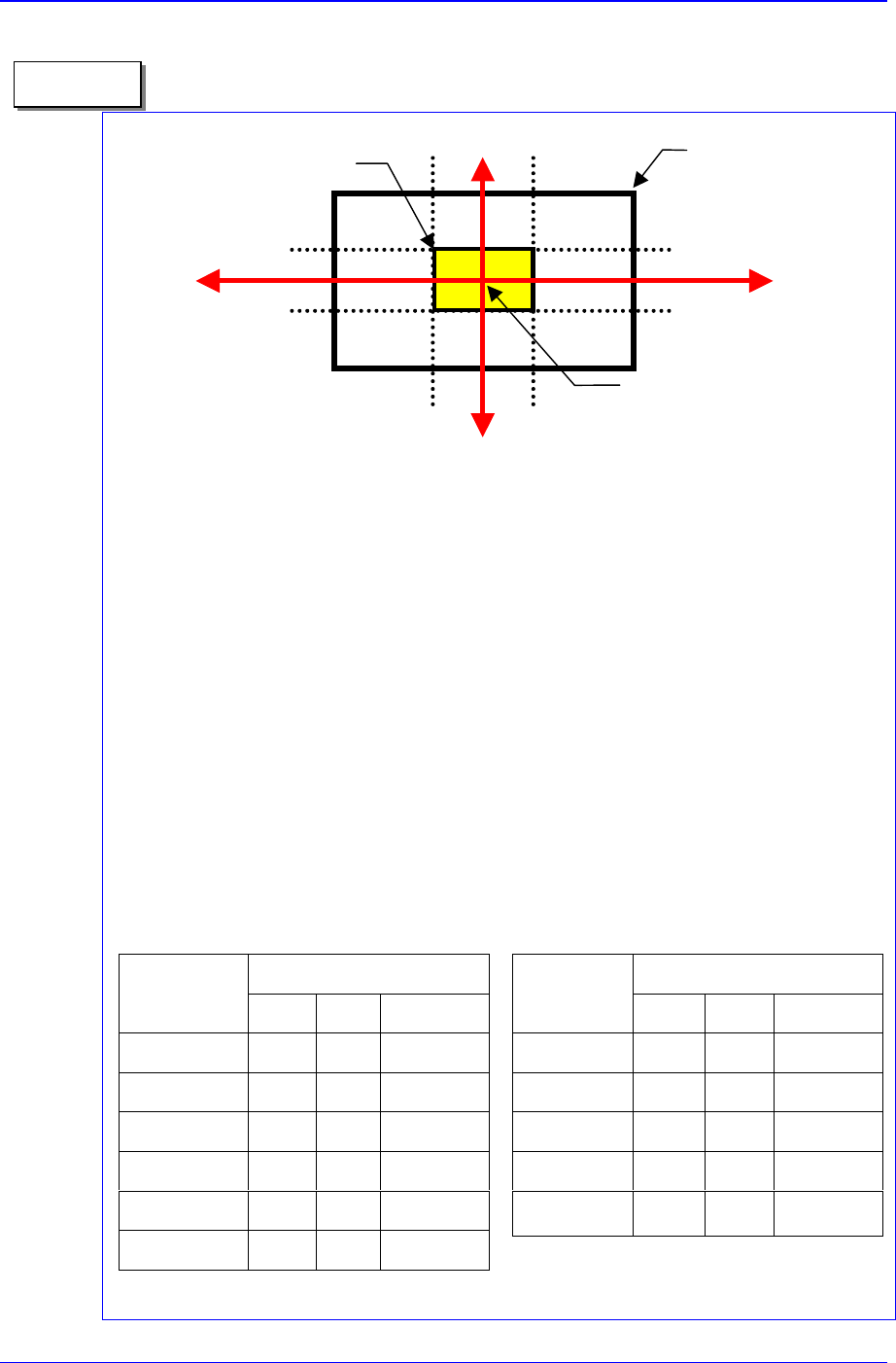
1. On 1/3 area of component pocket
First, check if the feeder is normally installed on the feeder base. If a feeder is
installed while a chip is stuck on the feeder base, the pickups position will be
deviated to that extent.
It is all right to use the feeder position (or pickups position) without changing it if the
crossing point of the red arrows on the vision monitor is within 1/3 area of
component pocket. When the feeder is installed normally, but the pickups position
and the crossing point of the red arrows are on the outside of 1/3 area of component
pocket, the feeder is considered to be abnormally installed. In this case, change the
feeder, teach again, and install it.
2. Component pickups point
Do not change the component pickups position if possible. Use the original coordinate
and it is recommended to use a value between 0.00 and 0.50 for Z axis coordinate.
3. Data value for normal chip components (1005 ~ 3216)
The equipment speed and time delay when registering regular chip components
are as follows. The data differs according to the chip size. As chip components
0603 and 1005 are tiny, it is best to place them under a condition different from
the one for other chip components.
However, they are not absolute. Rather, it is best to
use a value in these ranges to avoid putting strain on the equipment.
Component pocket area
1/3 area of component pocket
Crossing point of the re
d
arrows on the vision
monitor
1/3
2/3
1/3
2/3
Memo
Speed
Item
0603 1005 1608~3216
XY 1 1 1
R 1 1 1
Z Pick down 1 3 1
Z Pick up 3 2 1
Z Place down 1 1 1
Z Place up 1 1 1
Time Delay
Item
0603 1005 1608~3216
Pick up 0 20 30
Place 25 25 10
Vacuum off 0 0 0
Dump 100 100 100
Vacuum vac.
off
0 0 0