operation-cp45.pdf - 第220页
Samsung Component Placer CP-45F(V)/FS Operations Manual 11-66 Set the first empty lead in the lead group. As many leads as the number of miss are m issing. <Gap2 Start> column Set the second empty lead in the lea…
PCB Edit Command
11-65
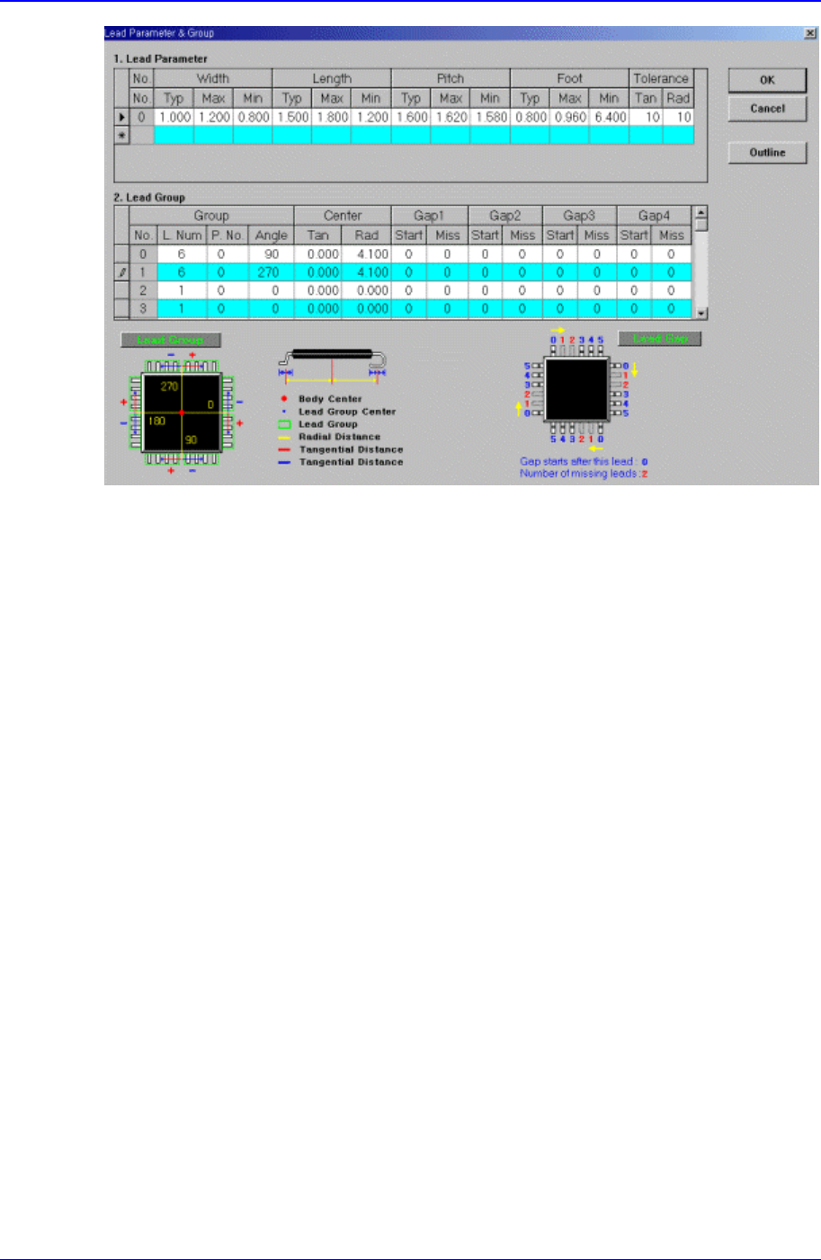
Figure 11-42. Screen showing “Lead Group” setting in the dialog box for “User IC Lead
Parameter & Group”
<Lead Group> group
Set the lead group.
<Group No.> column
Displays the lead group number. Applicable range is 0 – 15.
<Group L. Num> column
Set the number of leads the lead group has.
<Group P. No.> column
Set the lead parameter number referenced by the lead group. Applicable range is
0 – 7.
<Group Angle> column
Set on which side of the component the lead group exists. 0, 90, 180, and 270 in
the above figure denotes the angles.
<Center Tan> column
Set the distance from the component origin point (component center in general)
to the center of the lead group along the tangential line.
<Center Rad> column
Set the distance from the component origin point(component center in general) to
the center of the lead group along the normal line.
<Gap1 Start> column
Set the first empty lead in the lead group.
There are no leads after the lead on the starting number.
<Gap1 Miss> column

Samsung Component Placer CP-45F(V)/FS Operations Manual
11-66
Set the first empty lead in the lead group.
As many leads as the number of miss are missing.
<Gap2 Start> column
Set the second empty lead in the lead group.
There are no leads after the lead on the starting number.
<Gap2 Miss> column
Set the second empty lead in the lead group.
As many leads as the number of miss are missing.
<Gap3 Start> column
Set the third empty lead in the lead group.
There are no leads after the lead on the starting number.
<Gap3 Miss> column
Set the third empty lead in the lead group.
As many leads as the number of miss are missing.
<Gap4 Start> column
Set the fourth empty lead in the lead group.
There are no leads after the lead on the starting number.
<Gap4 Miss> column
Set the fourth empty lead in the lead group.
As many leads as the number of miss are missing.
<Outline> button
Displays the outline of the component on the vision monitor by using the set align
data.
PCB Edit Command
11-67
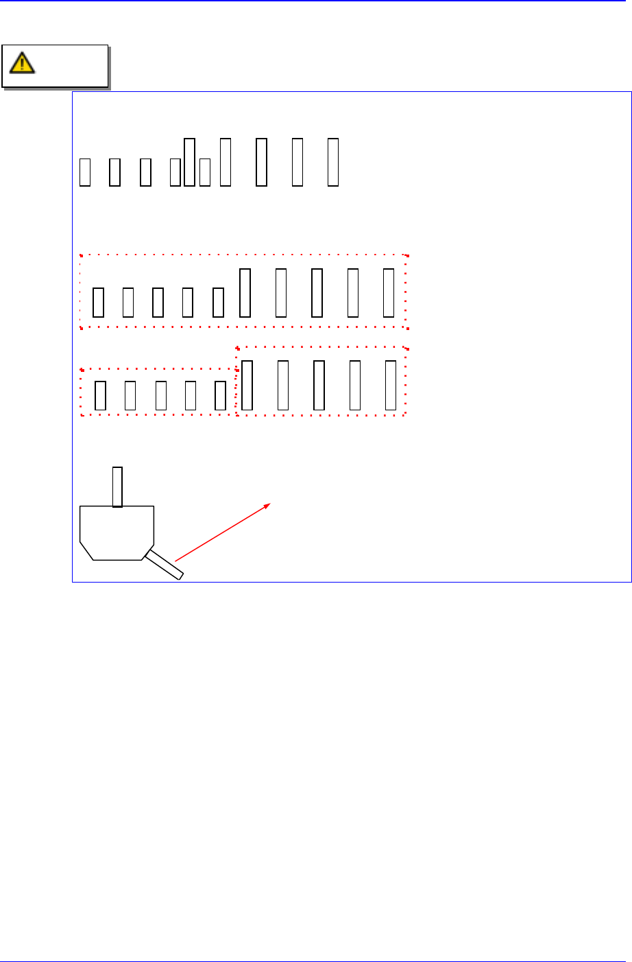
Restrictions
Adjacent lead groups cannot overlap.
Invalid. Because the two lead
groups are overlapped.
One lead group uses one lead parameter. In other words, a lead group should only
contain leads of the same type.
This lead group cannot be
registered as single lead group
because the lead parameters are
different.
These lead groups are registered
as separate lead group because
the lead parameters are different.
Leads groups are placed only at right angle directions.
In this case, this pin cannot be a lead.
Caution