operation-cp45.pdf - 第246页
Samsung Component Placer CP-45F(V)/FS Operations Manual 11-92 Move Cam: Selects T eaching Camera. Head1: Selects Head1. Head2: Selects Head2. Head3: Selects Head3. Head4: Selects Head4. Head5: Selects Head 5. Head6: Sele…
PCB Edit Command
11-91
grid. At this time, the device must be selected first. When pickups is successful, the
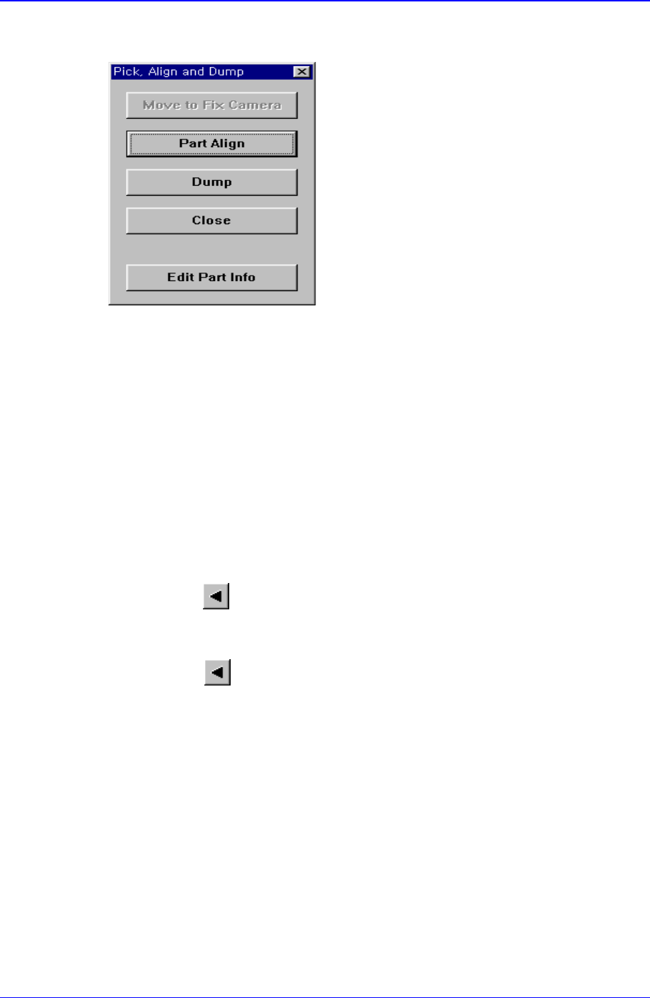
following dialog box is displayed.
<Move to Fix Camera> button
It is activated only when the corresponding component is aligned by the vision
camera and the alignment camera is the fix camera. When this button is clicked
on, the head block is moved to the fix camera.
<Part Align> button
Executes alignment of the corresponding component.
<Dump> button
Dumps the corresponding component to the specified dump box.
<Close> button
Closes the dialog box.
<Pocket Move> button
Moves the selected device to the pocket number set in <Current Pocket>.
<Move Prev>
button
Moves the selected device to the pocket number previous to the number set in
<Current Pocket>.
<Move Next>
button
Moves the selected device to the pocket number next to the number set in <Current
Pocket>.
<Current Pocket> group
<X>: Set the pocket number of the tray to move to or pick up from in X direction.
<Y>: Set the pocket number of the tray to move to or pick up from in Y direction.
<Pallet In> button
Loads the pallet to be ready for placement from the elevator of the tray feeder.
<Pallet Out> button
Release the pallet to be finished placement from the elevator of the tray feeder.
<Device> combo box
To move or to read in the position of the XY axis, select the corresponding device.
Available devices are as follows.

Samsung Component Placer CP-45F(V)/FS Operations Manual
11-92
Move Cam: Selects Teaching Camera.
Head1: Selects Head1.
Head2: Selects Head2.
Head3: Selects Head3.
Head4: Selects Head4.
Head5: Selects Head 5.
Head6: Selects Head6.
Beam: Selects Beam.
<Move> button:
Moves the XY axis of the device selected in <Device>. Before executing “Move”, the
cell in the grid corresponding to the desired position must be clicked on with a mouse
<Get> button:
Reads in the current position of the XY axis of the device selected in <Device>.
Before executing “Get”, the cell in the grid corresponding to the position to be read
must be clicked on.
<Install to Feeder Base> group
Displays the feeder base unit and slot number when the tray unit is set to the feeder
base.
<Feeder Base>
Displays the feeder base on which the corresponding tray unit is installed
currently. The numbers displayed are as follows.
0: Not installed on any feeder base.
1: Installed on Feeder Base1(Front Feeder Base).
2: Installed on Feeder Base2(Rear Feeder Base).
<Slot No.>
Displays the number of the feeder base slot in which the corresponding tray unit
is installed currently. The numbers displayed are as follows.
0: Not installed in any slot.
1 - 52: Installed in the corresponding number slot.
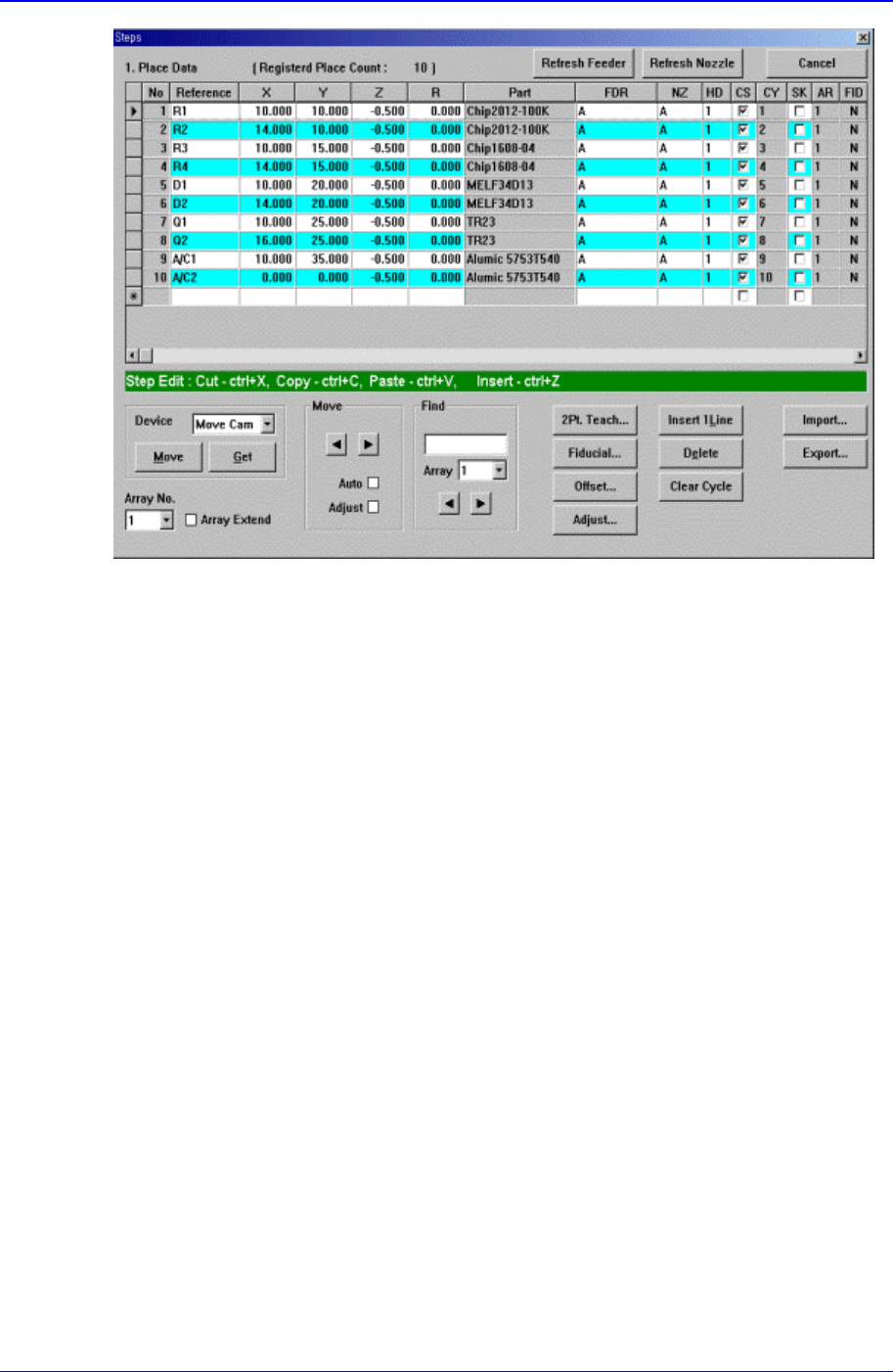
11.3. Step-Program
The <Step> command edits data on PCB placement points, component fiducial marks,
components to be placed, component supplying feeders, and nozzles to pick up
components. When this command is executed, the following initial screen is displayed.
PCB Edit Command
11-93
Figure 11-54 “Steps” Dialog box (Initial screen without placement point)
<1. Place Data> group
Set the edit data related to placement.
<Reference> column
Set the reference name of the placement point. In general, enter the value of R1,
R2, C1, and C2 on the PCB(up to 8 characters).
<X> column
Set the X position of the placement point.
<Y> column
Set the Y position of the placement point.
<Z> column
Set the Z position of the placement point.
<R> column
Set the R position(rotation angle of the placement component) of the placement
position.
<Part> column
Select the component to place.
<FDR> column
Select the feeder to supply the component.
<NZ> column
Select the nozzle to pick up the component.
<HD> column
Select the head to pick up the component.
<CS> column