operation-cp45.pdf - 第96页
Samsung Component Placer CP-45F(V)/FS Operations Manual 3-6 MOTOR FREE In case of an emergency , press this button to stop the operation immediately . It shuts off all power supplies except to the computer . It pe rfor…
Panel Operations
3-5
3.3. Button Manipulation of Teaching Box
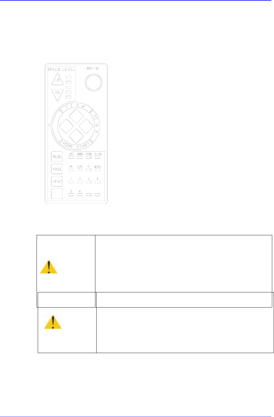
A teaching box is used for manipulating the head, or returning to the original position. A
teaching box also can be used only when the yellow lamp in the signal tower. The buttons
on the teaching box are explained below:
FREE
Figure 3-3. Teaching Box
S
peed level Up/Down
This selects operation speed in the jog mode. After the jog mod has been selected, the
equipment operation is speeded up if <Up> button is pressed, or slows down if
<Down> button is pressed. The operation speed can be selected in 5-steps.
Warning
During teaching, the operator or people near the operator
could be injured due to operation error or insufficient
checking of surroundings.
Before start teaching, check the device to teach one more
time, and check whether there is any worker near the
machine.
Caution
Placing a floppy disk near the area where the magnet is
attached on the back of Teaching Box could erase the
data in it.
Do not place a floppy disk near the area where the magnet
is attached on the back of Teaching Box.

Samsung Component Placer CP-45F(V)/FS Operations Manual
3-6
MOTOR FREE
In case of an emergency, press this button to stop the operation immediately. It shuts
off all power supplies except to the computer. It performs the same function as the
<EMG> on the operation panel of the main body.
◀▶▲ ▼
button
These buttons indicate the translational or rotational direction of movement or
rotation of each axis. Each mode or axis has different operation.
If Mode=Jog or Bang, Axis=XY have been selected:
▲
: The head part is moved in the +Y-direction.
▶
: The head part is moved in the +X-direction.
▼
: The head part is moved in the -Y-direction.
◀
: The head part is moved in the -X-direction.
If Mode=Jog or Bang, Axis=Z/R have been selected:
▲
: The nozzle is lifted in the +Z direction.
▶
: The nozzle is rotated in the clockwise direction.
▼
: The nozzle is lowered in the -Z direction.
◀
: The nozzle is rotated in the counterclockwise direction.
If Mode=Home has been selected
▲
: Ignored.
▶
: Ignored.
▼
: The head is moved to the original position (Return to home position).
◀
: Ignored.
Mode
Modes such as Jog, Bang, and Home are selected. As this button is pressed, LED for
indicating the corresponding mode is alternately turned on in the order of Jog
⇒
Bang
⇒
Home
⇒
Lights-out
⇒
Jog ... Each mode functions as follows:
Jog: Each axis is moved by this mode.
Bang: Each axis is moved by a minute distance by this mode.
Home: The original position (origin point) of each mode is found by this mode.
Axis

Panel Operations
3-7
An object to be operated on is selected. As this button is pressed, LED is alternately
turned on in the order of XY
⇒
Z/R
⇒
S
⇒
W/Cv
⇒
Lights-out
⇒
XY..., and the
object of operation is switched accordingly. Each functions as follows:
XY: A moving object is designated in the XY-direction of the head.
Z/R: A moving object is designated in the Z and rotational directions of the
nozzle.
S: A moving object is designated in rotational directions of the mirror.
W/Cv: A moving object is designated in the X-direction and Y-direction of the
conveyor.
Lights-out: For Home mode selected, returns to the original position for X, Y, Z
and R.
Head
If a mode other than Home is selected in the Mode and Z/R in the Axis is selected,
the corresponding number for the head that is the object of operation is designated.
3.4. Emergency Stop
The methods of stopping this equipment in emergency include a stop by the operator and
a system emergency stop in which the system detects a specific abnormality and effects
on emergency stop.
3.4.1. Operator emergency stop
The operator emergency stop is used to stop the operation for some urgent reasons. In this
case, <EMG> switch on the operation panel or <MOTOR FREE> button on the teaching
box is pressed. During the operator emergency stop, operation of this equipment is not
possible, and all power supplies excluding that to the computer are cut off.
The operator emergency stop can be released by first removing the cause of the
emergency stop, releasing <EMG> switch, and then pressing <Reset> switch.
In addition, opening the front or rear door puts the system in the emergency stop status.
The emergency stop status can be released by closing the door and pressing <Reset>
switch in this case.