operation-cp45.pdf - 第195页
PCB Edit Command 1 1-41 Figur e 1 1-28. “ Align T ype = V ision, Package Gr oup = CHIP-Rect ” dialog box <Camera No.> combo box Select the camera to recognize the component. <Light Control> button Select …
Samsung Component Placer CP-45F(V)/FS Operations Manual
11-40
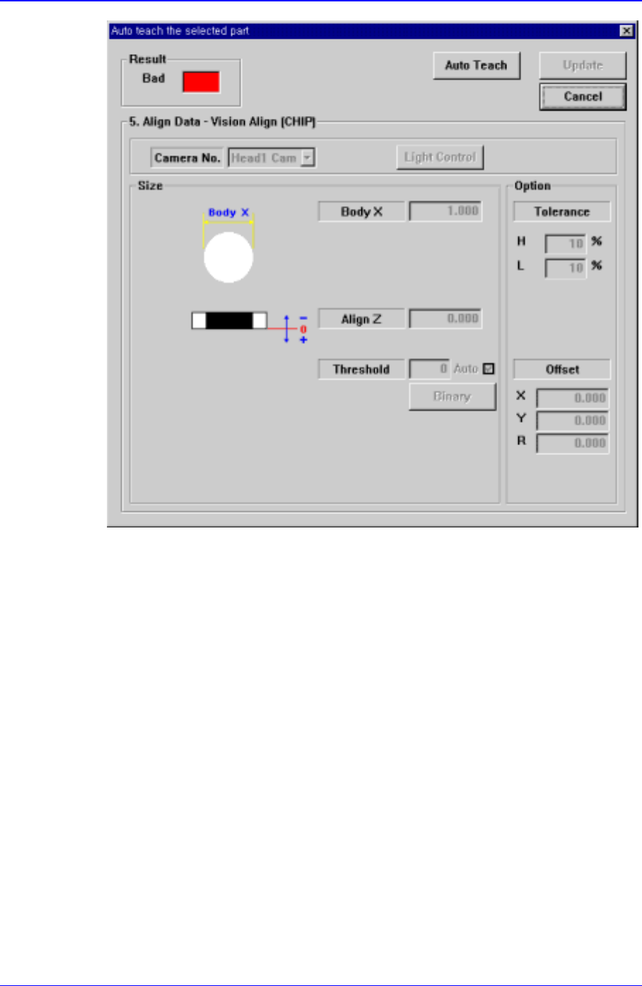
Figure 11-27. . “Auto Teach the selected part-Bad” message box
The same as the Figure 11-28, but the <Update> button is inactivated.
<Repeat…> button
Performs the component recognition test repeatedly. It is not explained here since it is
for debugging.
11.1.2. CHIP-Rect component data setting
Set the align data for rectangular CHIP components.
PCB Edit Command
11-41
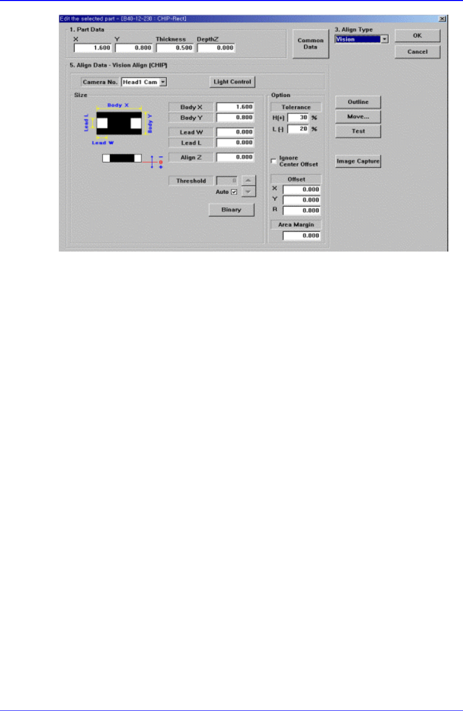
Figure 11-28. “Align Type = Vision, Package Group = CHIP-Rect” dialog box
<Camera No.> combo box
Select the camera to recognize the component.
<Light Control> button
Select the light for the camera to recognize the component.
<Size> group
Set the align size.
<Body X> edit box
Set the component size in X direction.
<Body Y> edit box
Set the component size in Y direction.
<Lead W> edit box
Set the length of lead in X direction.
<Lead L> edit box
Set the length of lead in Y direction.
<Align Z> edit box
Set the height for recognition. Based on the component surface, if the top is to be
recognized, set - value and if the bottom is to be recognized, set + value.
<Threshold> edit box
When there is a pre-treatment process for component recognition and the gray
level image is converted into binary, it is the value used as the criteria to
determine black and white.
The value range is 0 – 255(0: black, 255: white), and this value serves to
differentiate the component from the background. When the set value is 0, the
value is set automatically during component recognition.
<Auto> check box

Samsung Component Placer CP-45F(V)/FS Operations Manual
11-42
Check it if the <Threshold> value is set automatically.
<Binary> button
Displays the binary image of the component on the vision monitor screen.
<Option> group
Set the align option data.
<Tolerance H> edit box
Set the highest tolerance for component recognition with a percentage.
<Tolerance L> edit box
Set the lowest tolerance for component recognition with a percentage.
<Ignore Center Offset> check box
In the case of Chip components, Center Offset is not checked during vision check.
<Offset X> edit box
Set the X offset value to be added when the component is placed. (After the
component is recognized, it is the value added after the placement point
adjustment.)
<Offset Y> edit box
Set the Y offset value when the component is placed (After the component is
recognized, it is the value added after the placement point adjustment)
<Offset R> edit box
Set the R offset value to be added when the component is placed (After the
component is recognized, it is the value added after the placement point
adjustment)
<Outline> button
Displays the outline of the component on the vision monitor by using the set align
data.
<Move…> button
Performs component pickups or moves to the fix camera.
<Test> button
Tests component recognition by using the set align data.
<Image Capture> button
Helps to specify the optimum lighting value. The lighting is gradually changed
automatically and the images are saved. The user can check the best image and
identify the optimum lighting value.
11.1.3. Melf component data setting
Set the align data for Melf components.