operation-cp45.pdf - 第166页
Samsung Component Placer CP-45F(V)/FS Operations Manual 11-12 Head1: Selects Head 1. Head2: Selects Head 2. Head3: Selects Head 3. Head4: Selects Head 4. Head5: Selects Head 5. Head6: Selects Head 6. <Move> butto…
PCB Edit Command
11-11
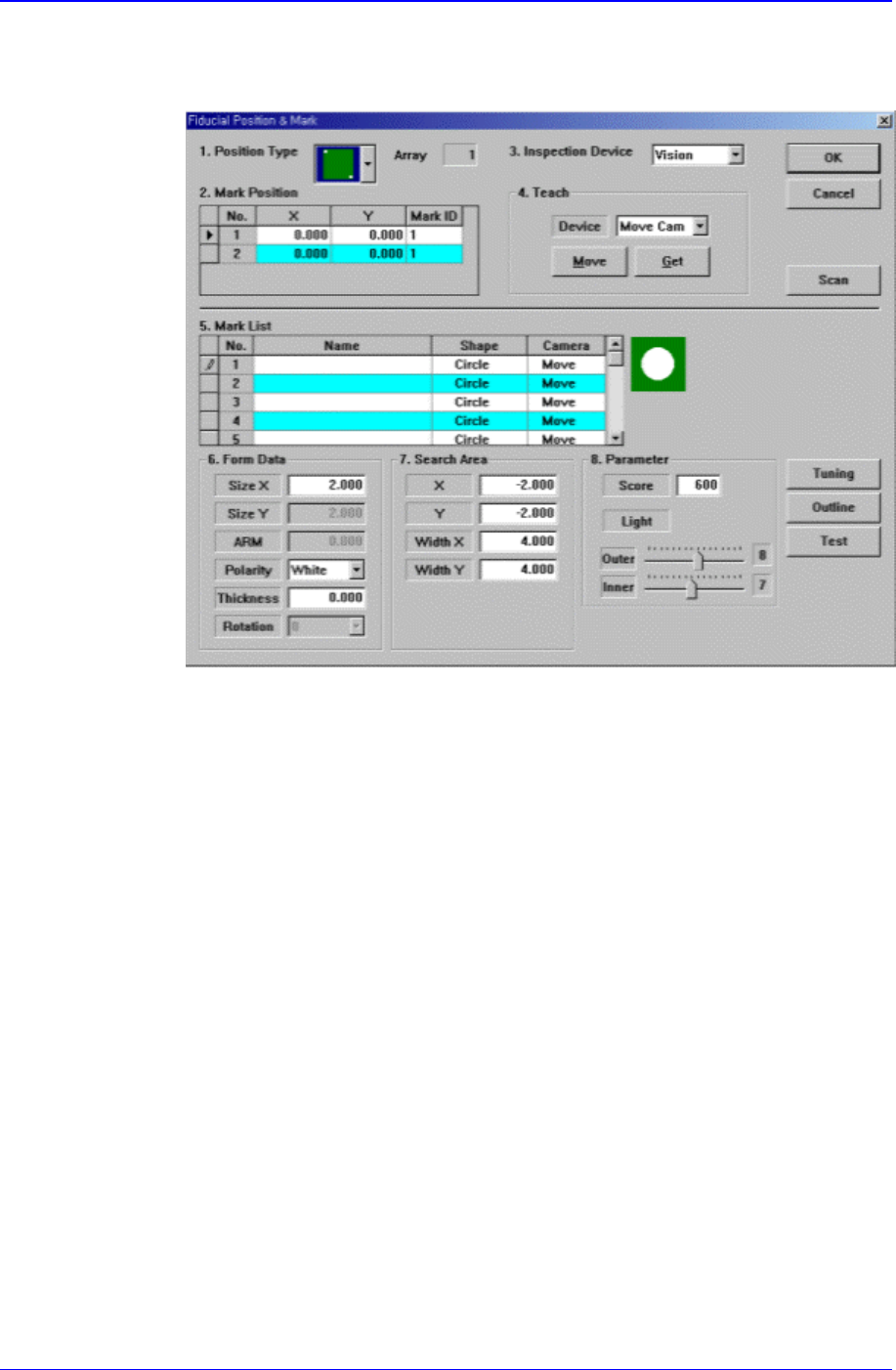
If <Position Type> is not “None”, the number of data corresponding to the
number of fiducial marks selected are generated. For example, when “2 Panel” is
selected, the following dialog box is displayed.
Figure 11-13. “Fiducial Position & Mark” dialog box(When the Position Type is “2
Panel”)
<No> column
A serial number of the position of fiducial mark.
<X> column
The X position value of fiducial mark.
<Y> column
The Y position value of fiducial mark.
<Mark> column
The mark ID value of fiducial mark. This value must be set from a series of
numbers in <5. Mark List>.
<3. Inspection Device> combo box
Select the device to inspect the fiducial mark. Available devices are as follows.
Vision: Recognizes with the move camera in the head block.
<4. Teach> group
Used to move the XY axis of the equipment to the specified position or to read in
the current position of the XY axis.
<Device> combo box
To move the XY axis or to read in the position, select the corresponding
device. Available devices are as follows.
Move Cam: Selects Teaching Camera.
Samsung Component Placer CP-45F(V)/FS Operations Manual
11-12
Head1: Selects Head 1.
Head2: Selects Head 2.
Head3: Selects Head 3.
Head4: Selects Head 4.
Head5: Selects Head 5.
Head6: Selects Head 6.
<Move> button
Moves the XY axis to the device selected in <Device>. Before executing
“Move”, the cell in the grid corresponding to the desired position must be
clicked on with a mouse.
<Get> button
Reads in the current position of the XY axis selected in <Device>. Before
executing “Get”, the cell in the grid corresponding to the desired position
must be clicked on with a mouse.
<OK> button
Saves the fiducial mark data and closes the “Fiducial Position & Mark” dialog
box.
<Cancel> button
Closes the “Fiducial Position & Mark” dialog box without saving the fiducial
mark data.
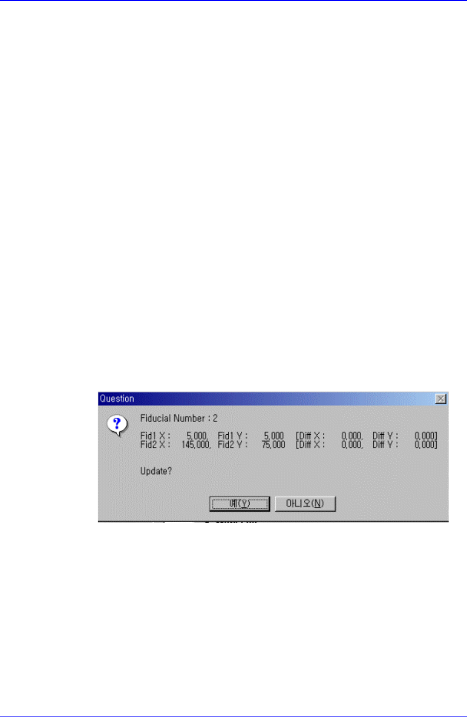
<Scan> button
Executes a scan test on the set fiducial mark. The scan test inspects the actual
mark by using the set fiducial mark position and mark data and displays the
result as follows.
The position of the fiducial mark displayed on the above screen is the position of
the mark obtained through the scan test. If you want to update the value, click on
“Yes,” if not click on “No”.
PCB Edit Command
11-13
<5. Mark List> group
A list of fiducial mark shape data.
<No> column
A serial number of fiducial mark shape
<Name> column
The name of the fiducial mark(Up to 10 characters)
<Shape> column
Select the shape of fiducial mark. Available shapes are as follows.
Circle: Circular shape fiducial mark.
Diamond: Diamond shape fiducial mark.
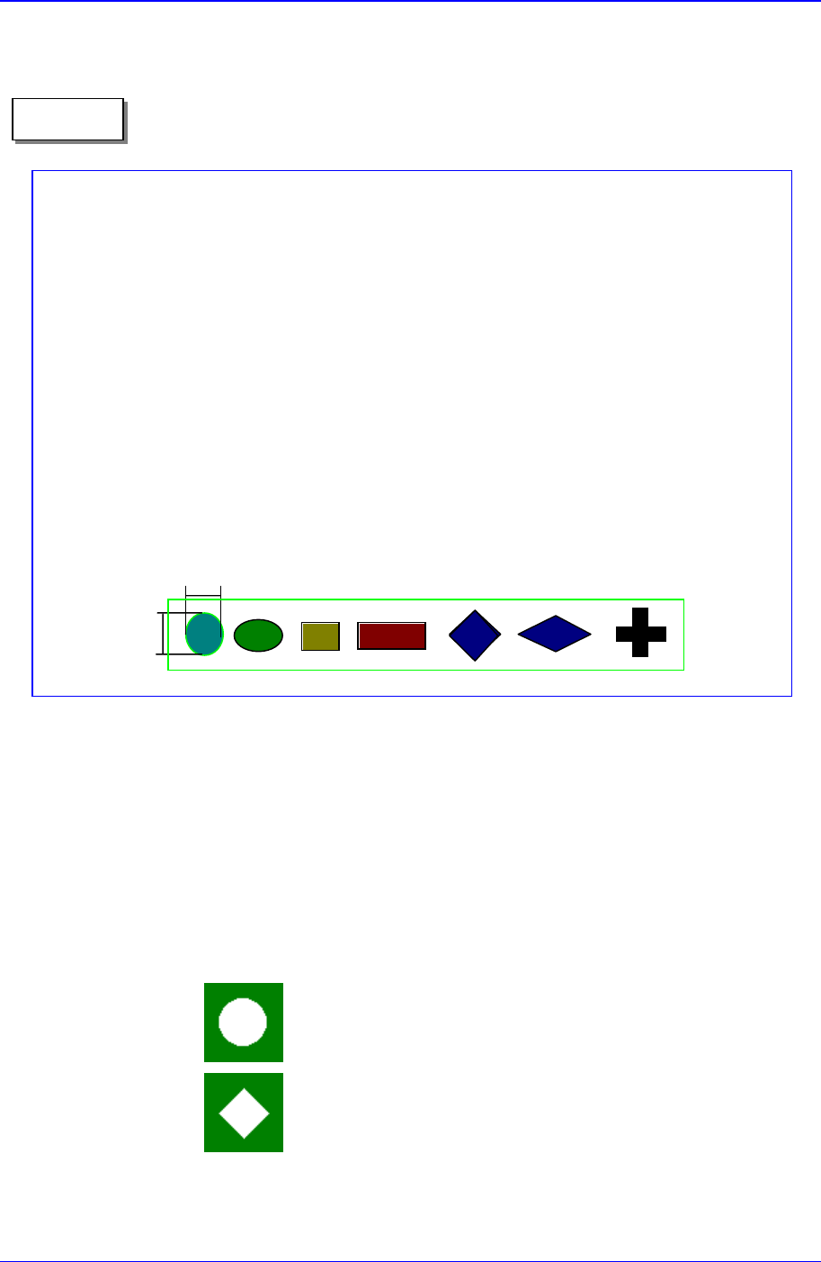
On Fiducial Marks
A fiducial mark has to satisfy several shape and material conditions. During
the design of PCB, the following precautions should be taken.
Seven patterns of fiducial mark shapes are possible as shown in the figure
below (top/bottom symmetry or right/left symmetry)
For the size of A, over 2.0 ㎜ is recommended. The width of mark senso
r
beam is about ø0.7 ㎜ measured from the surface of PCB.
Make sure that any changes in color or shape(solder resist, lead pattern)
that can cause error should not be found within 2.0 ㎜ of fiducial mark's
outer edges.
Make sure that the shading difference exits between the fiducial mark and
the board surrounding it.
To ensure search accuracy, coat the surface of the fiducial mark with
copper or lead so that the surface does not reflect. The line shaped fiducial
marks can not be searched with Beam.
A
A
Memo