operation-cp45.pdf - 第294页
Samsung Component Placer CP-45F(V)/FS Operations Manual 15-8 15.5. Origin [F5] Sets the origin of each factor . When this button is clicked on, the following dialog box is displayed. Figur e 15-7. “ Sys. Setup : Origin P…
Sys.Setup Command
15-7
Set the X offset value for Beam1.
<Beam#1 Y> edit box
Set the Y offset value for Beam1.
<Beam#2 X> edit box
Set the X offset value for Beam2.
<Beam#2 Y> edit box
Set the Y offset value for Beam2.
<Z Offset Measure Point> group
Set the X, the Y and the Z values for the Z Offset Measure Point of each heads.
<Detect Offset>button
Set the Offset values of each heads automatically.
<Update> button
Transmits the set data to the equipment and closes the dialog box.
<Cancel> button
Ignores the set data and closes the dialog box.
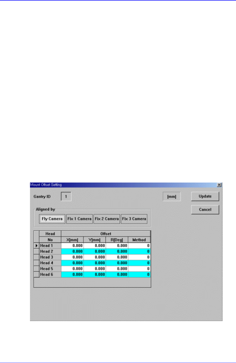
15.4. Offset [F5]
Sets the Offset value of the equipment.
When this button is clicked on, the following dialog box is displayed.
Figure 15-6. “Sys. Setup : Offset Setting” dialog box
Samsung Component Placer CP-45F(V)/FS Operations Manual
15-8
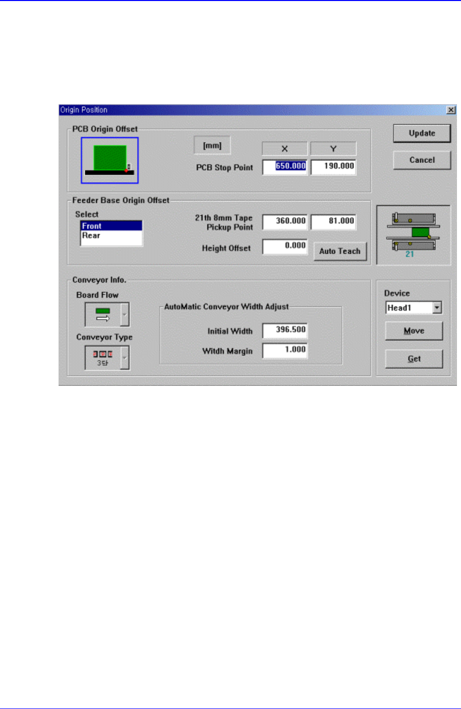
15.5. Origin [F5]
Sets the origin of each factor.
When this button is clicked on, the following dialog box is displayed.
Figure 15-7. “Sys. Setup : Origin Position” dialog box
<PCB Origin Offset> group
Set the offset value between the equipment origin and the PCB board origin.
<PCB Stop Point> edit box
Set the PCB board origin.
<Feeder Base Origin Offset> group
Set the data on feeder base.
<Select> list box
Select the front or rear feeder base.
<21th 8mm Tape Pickup Point> edit box
To set the feeder base origin, install a 8mm tape feeder in the 21st slot of each
feeder base and set the feeder base origin by using the pickups point of this
feeder.
<Height Offset> edit box
Set the Z value of the feeder base origin.
<Conveyor Info.> group
Set the data on conveyor.
<Board Flow> combo box

Sys.Setup Command
15-9
Displays the direction of conveyor movement. To change the direction of
conveyor movement, please contact this equipment manufacturer.
<Conveyor Type> combo box
Displays the type of the conveyor. To change the type of the conveyor, please
contact this equipment manufacturer.
<AutoMatic Conveyor Width Adjust – Initial Width> edit box
When the conveyor width is adjusted automatically, set the initial value of
conveyor width.
<AutoMatic Conveyor Width Adjust – Width Margin> edit box
Set the tolerance for conveyor width.
<Device> combo box
To move or to read in the positions of the XY and Z axes, select the corresponding
device. Available devices are as follows.
Move Cam: Selects Teaching Camera.
Head1: Selects Head1.
Head2: Selects Head2.
Head3: Selects Head3.
Head4: Selects Head4.
Head5: Selects Head5.
Head6: Selects Head6.
<Move> button
Moves the XY, and Z axes to the device selected in <Device>. At this time, the edit
box corresponding to the position to move to must be clicked on with a mouse.
<Get> button
Reads in the current position of the XY and Z axes of the device selected in <Device>.
At this time, the edit box corresponding to the position to be read must be clicked on
with a mouse.
<Update> button
Transmits the set data to the equipment and closes the dialog box.
<Cancel> button
Ignores the set data and closes the dialog box.
15.6. Tray [F6]
Sets the data on the tray feeder.
When this button is selected, the following dialog box is displayed.