operation-cp45.pdf - 第43页
Features and Scope of Equipment 1-5 1.2.4.1. General features Speed The optimum condition for the tact tim e is specified. The placed Component : 1608 chip T ime Measurement The measured time from the first pickups…

Samsung Component Placer CP-45F(V)/FS Operations Manual
1-4
1.2.2.2. Stage vision recognition system(For CP-45FV /45FS)
Table 1-3. Applicable Component Sizes (Vision Recognition System)
CP-45FV / 45FS
Option
Classification
Standard
FOV35mm
FOV20mm FOV45mm
IC , Connector
~ □ 17mm: 0.3 mm pitch
~ □ 32mm: 0.4 mm pitch
~ □ 40mm: 0.5 mm pitch
( MFOV for more than
32mm)
Chips 1005~
~ □ 17mm: 0.3 mm
pitch
~ □ 32mm: 0.4 mm pitch
~ □ 42mm: 0.5 mm pitch
BGA
~ □ 32mm: 1.0mm pitch
~ □ 17mm: 0.5mm
pitch
~ □ 42mm: 1.0mm pitch
1.2.3. The placement precision
The placement precision for applicable components type is shown in Table 1-4, and is
applicable to general components usage as well.
Table 1-4. The placement Precision
Classification
Placement
precision
Remarks
Chip 0603
Chip 1005
± 0.08
± 0.1
FOV15mm Flying vision (CP-45FS)
± 0.065 FOV25mm Flying Vision(□ 25mm: 0.5 pitch)
QFP
± 0.040 FOV35mm Stage Vision(□ 17mm: 0.3 pitch)
± 0.065 FOV25mm Flying Vision(□ 17mm: 0.75 pitch)
BGA
± 0.080 FOV35mm Stage Vision(□ 32mm: 1.0 pitch)
± 0.065 FOV22mm flying Vision(□ 22mm: 0.5mm pitch)
Connector
± 0.05 FOV35mm Stage Vision(□ 32mm: 0.65mm pitch)
1.2.4. The pick & place cycle time
The descriptions given below refer to the best performance that can be obtained from the
pick & place cycle time. The actual cycle time can vary depending on the size of PCB,
frequency of the nozzle replacement, etc.
Features and Scope of Equipment
1-5
1.2.4.1. General features
Speed
The optimum condition for the tact time is specified.
The placed Component : 1608 chip
Time Measurement
The measured time from the first pickups to return of the machine to the original
position following the final placement.(Off-line time, i.e., the time for recognizing the
fiducial mark, or PCB feed time, is excluded.)
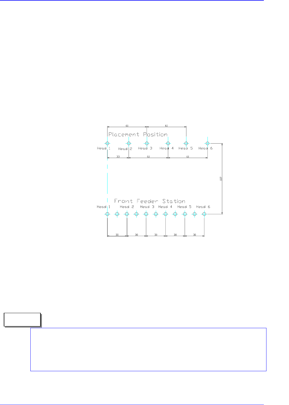
Figure 1-2. The Summary for Measuring the Tact Time (6 Heads Simultaneous Pickups, Each
heads place)
The above speed is for the pick & place cycle time under the optimum conditions
(rounded off to 1msec). The experimental conditions is under using a very new
equipment with a taped PCB at the factory site, therefore, in actual placement, it can vary
according to the placement conditions.
Memo
Samsung Component Placer CP-45F(V)/FS Operations Manual
1-6
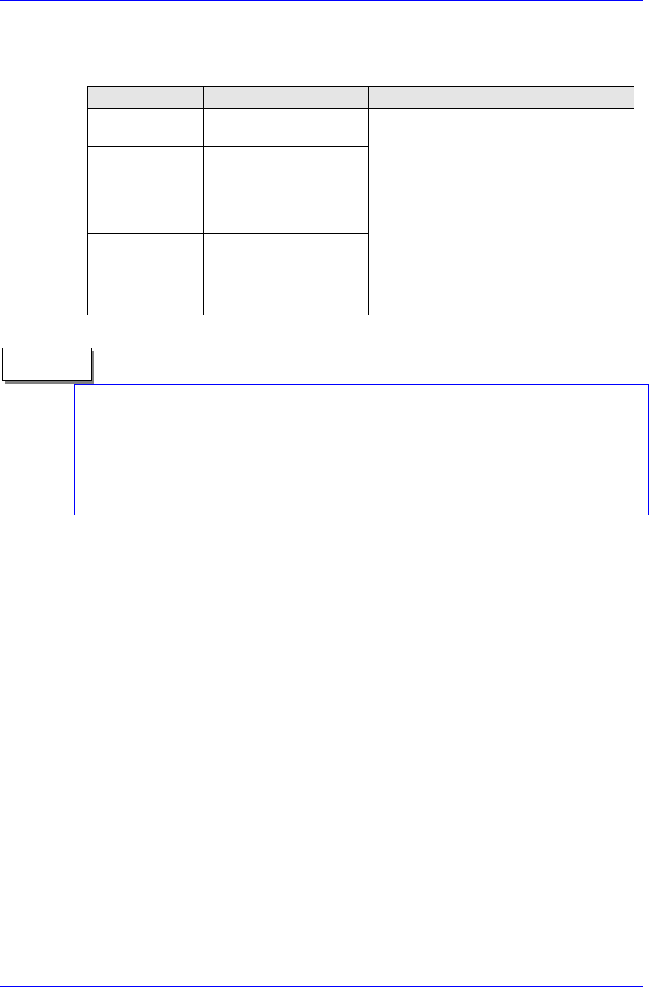
1.2.4.2. The pick & place cycle time for each model
Table 1-5. The pick & place Cycle Time for Each Model
Classification CP-45FV Remarks
Chip
0.197sec / component
(1608)
QFP
0.75 sec / component
(Flying Vision)
1.6 sec / component
(Stage Vision)
Connector
0.5 sec / component
(Flying Vision)
1.6 sec / component
(Stage Vision)
Simultaneous pickups under the optimum
conditions
Note) In the case of micro chips, lower it to
a proper speed by reducing the speed or
adjusting the delay variable according to the
placement status.
.Based on the optimum condition of QFP 80
(Y100mm, 100mm)
. Based on the optimum condition of black,
same interval, symmetrical type,
(Y 100mm , X 100mm)
The above are for the pick & place cycle time under the optimum conditions (rounded-off
to 1msec). In actual placement, the conditions that determine the cycle time may vary
depending on many factors such as the type of components, size of PCB, placement
position, etc. For more detailed information, please contact our Business Department or
C/S Center.
Memo