operation-cp45.pdf - 第91页
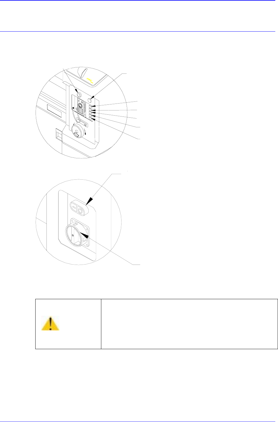
Panel Operations 3-1 Chapter 3. Panel Operations 3.1. Switching of Operation Panel Figur e 3-1. Operation Panel S witching operation on the operation panel is described below: <Isolation> switch Has a function of…
Samsung Component Placer CP-45F(V)/FS Operations Manual
2-38
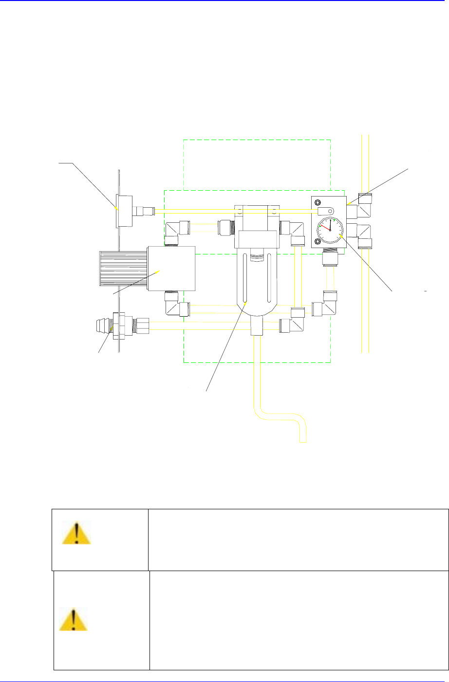
2.16. Pneumatic Part
Generally, the air pressure values in the range of 4.5 – 5.5 kgf/㎠ s can be set and used.
The air flows through the main inlet at the rear bottom end of the equipment. One portion
is used for operating the multi-cylinder of the feeder station, another portion is used for
driving ANC, still another portion is used for generating vacuum in the head, and the
remaining portion is used for operating stoppers of the conveyor.
Pressure Gauge (View)
Regulator
Coupler (male)
Air Filter & Auto Drainer
Manifold
Pressure with
Auto Switch
Figure 2-25. Main Inlet of Pneumatic Part
Warning
Failure of disconnecting air pressure and power supply for
the repair and maintenance of machine could result in
severe injury.
Be sure to disconnect air pressure and power supply for the
repair and maintenance of machine.
Caution
If the pressure is under the appropriate level, the machine
might operate irregularly.
In general, 4.5~5.5 bar is appropriate for the air pressure.
Panel Operations
3-1
Chapter 3. Panel Operations
3.1. Switching of Operation Panel
Figure 3-1. Operation Panel
S
witching operation on the operation panel is described below:
<Isolation> switch
Has a function of supplying or stopping the main power to the equipment. Power is
supplied to a controller by turning the switch. A power lamp is lighted and a working
screen is shown on the programming monitor after a short delay. During the initial
Warning
Pressing the Start switch without checking the presence
of worker nearby could cause injury. Be sure to check if
there is any worker near the machine before pressing the
Start switch.
Buzze
r
Emergency switch
Ready switch
Start switch
Stop switch
Reset switch
Front Feeder CHG. switch
Main start switch
Isolation switch

Samsung Component Placer CP-45F(V)/FS Operations Manual
3-2
stage, power is not turned on for the drivers such as motor. The power should be
turned off only after terminating the MMI. If the power is suddenly turned off, the
data and the main body may be damaged and the equipment malfunction may occur
at the next power up.
<
M
a
in start> switch
Power is supplied by first pressing the green switch of a main start switch in order to
supply power to the power systems such as a motor. To cut off the power supply,
press the red switch.
<Ready> switch
This is a switch for initiating the operation of this equipment. The power is supplied
to the driving systems such as motor. It is used to put the equipment into the standby
status after power-up. <EMG (emergency stop)> switch can be pressed to release the
standby state.
<Start> switch
This is a switch for initiating the operation of this equipment. Automatic operation is
initiated if this switch is pressed.
This switch can be activated for the following cases:
Temporary stop status of operation by <Stop> switch during automatic operation.
Error stop status that can be restarted.
<Stop> switch
This is a switch for temporary stopping of the operation. Automatic operation of this
equipment is temporarily stopped if this switch is pressed. If this switch is pressed
while the placement is in progress, the operation is stopped after the present operation
is completed. This switch can also be used for turning off alarm sound due to an error.
<Reset> switch
Warning
If power supply is cut off suddenly, it could result in the
damage of data and machine.
And the machine might be damaged due to abnormal
operation when power is supplied again.
Before turning off power, be sure to end the MMI, turn
off the isolation switch, then turn on the isolation switch
after 5-10 seconds.