operation-cp45.pdf - 第226页
Samsung Component Placer CP-45F(V)/FS Operations Manual 11-72 Figur e 1 1-44 “ Ball Gap of BGA components-Initial status ” dialog box The grid displays the current ball status. The white dot indicates the ball. T o remov…

PCB Edit Command
11-71
Select the algorithm for BGA component recognition. Available algorithms are
as follows.
Ball: Recognizes by using the ball only. Used for the BGAs that have distinct
balls as in PBGA.
Ball & Body: Considers both the body and the ball. Used for the BGAs for which
it is difficult to distinguish between the body and the ball as in CBGA.
<Insp Ball Num> edit box
Select the number of balls to inspect. Available numbers of balls are as follows.
Full: Inspects all balls. It is good for accuracy, but inspection takes long time.
3x3: Inspects 3x3 balls counting from both ends of the corners at opposite angles
of the component.
4x4: Inspects 4x4 balls counting from both ends of the corners at opposite angles
of the component.
5x5: Inspects 5x5 balls counting from both ends of the corners at opposite angles
of the component.
6x6: Inspects 6x6 balls counting from both end of the corners at opposite angles
of the component.
7x7: Inspects 7x7 balls counting from both ends of the corners at opposite angles
of the component.
<Outline> button
Displays the outline of the component on the vision monitor by using the set align
data.
<Move…> button
Performs component pickups or moves to the fix camera.
<Test> button
Performs the component recognition test by using the set align data.
<Auto Teach> button
Automatically finds out the component align data.
<Ball Gap…> button
If there are any missing balls in the ball arrangement, sets the empty balls. It is
activated only when the <Grid Type> is “Regular”.
When this button is clicked on, the following dialog box is displayed.

Samsung Component Placer CP-45F(V)/FS Operations Manual
11-72
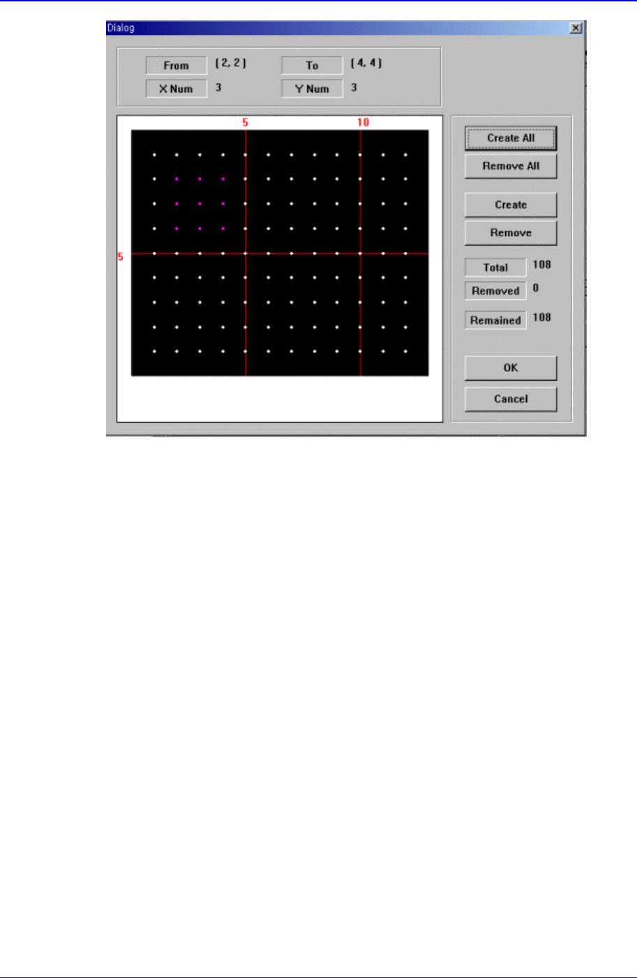
Figure 11-44 “Ball Gap of BGA components-Initial status” dialog box
The grid displays the current ball status. The white dot indicates the ball. To remove
balls in a certain area, the area should be specified first. The area to select can be set
by pressing the left button of the mouse, drag it to the desired area and release it. The
balls in the selected area change color. The following screen shows a case where 25
balls in total, from the ball at (4,4) to the ball at (10,10), 5 balls in X direction and 5
balls in Y direction, are selected.
PCB Edit Command
11-73
Figure 11-45 “Ball Gap of BGA component-when there is a selected area” dialog box
<Create All> button
Creates all balls.
<Remove All> button
Removes all balls.
<Create> button
Creates balls in the selected area.
<Remove> button